Why do I need a transistor tester and what does it measure
What it is
The transistor tester is a universal digital measuring device capable of checking not only transistors, but also other elements. Both semiconductor - thyristors, triacs, diodes and others, and passive elements, for example: resistors, capacitors, inductor.
However, in most cases, the above elements are more convenient and faster to check for serviceability. multimeter, but this device is still useful, as an ESR tester.
ESR is equivalent series resistance, an important parameter for electrolytic capacitors. Due to the impossibility of measuring it with a household multimeter, and specialized ESR meters are expensive, it is much more difficult for beginners to diagnose faults in electronic circuits.
Using transistor testers, you can measure ESR with normal accuracy, and the cost of these devices lies in the range of 10-20 dollars, depending on the model.
This device is often called the "Marcus Transistor Tester," which is partly wrong. Initially, the idea of creating a universal tool for checking radio components originated with Marcus Freieck, later Karl Heinz Kubbeler continued his work. And the so-called transistor testers with aliexpress are nothing more than copies of the Marcus tester, instruments modified by enthusiasts. In this connection, they do not have a specific manufacturer, but there is a wide community on the Internet. Thanks to this, it is easy to find Russian-language firmware and instructions for upgrading the device.
Types of Testers
In the electronics market, various modifications of transistor testers are presented, we will consider popular options.
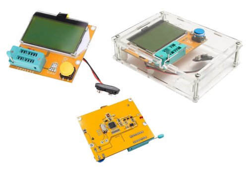
LCR-T4 or T3 - a yellow card and one key, the device is powered by a "crown" battery (9V). It only knows how to check elements with 2 or 3 outputs (a list is given below). This device has a two-color backlight synthesizing LCD display with a resolution of 128x64 pixels. There are no obvious differences between T4 and T3, most likely there is some difference in firmware.
It can be delivered in the form of a kit-kit (constructor) for self-assembly, as well as in finished form, most often without a case. Some sellers from Aliexpress offer a complete set with an acrylic transparent case, or a case made of opaque plastic in white or black. Self-assembly constructor can be supplied with a red board and a microcontroller in the DIP28 package. The cost of the device is from 4 (without the case) to 10 (in the case) dollars.
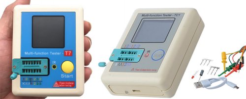
TC-1, TC-6, T7 is always delivered in a white case.It features a large number of functions, there is a window for checking IR diodes, as a result of which the code transmitted by the diode is displayed. This way you can check the remote controls. The display of the TC-1 is color, with a resolution of 160x128 pixels. Management is also carried out by pressing 1 button.
The main feature of the TC-1 and its counterparts - Power is supplied from the built-in battery, which is charged via a micro-USB connector. The cost of the device is in the range of 13-20 dollars.
You can see a comparison of the performance and other features of these devices in this video:
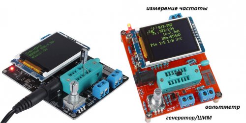
The GM328 is the most advanced model with an encoder and color display, but there are also cheaper two-color display options. It is delivered both on the board and in an acrylic transparent case (or from other materials). Usually it is a black or red color board. Power can be supplied either from the “crown” or from the power supply through the connector on the board. The control is carried out by the encoder, turning or pressing which you select the desired menu item. Distinctive features are the presence of a frequency generator, a frequency meter, a PWM signal generator (duty cycle varies from 0 to 99%) and some other useful functions. The cost of the device is in the range of 10-15 dollars.
I repeat that all the devices have functions for measuring the parameters of transistors and passive components, with approximately the same accuracy. It depends on the assembly and accuracy of the components in the microcontroller harness. All testers are based on the Atmega328 microcontroller, from AVR. At the same time, it makes no sense to list the full functionality and characteristics of each, since there are firmware with a frequency meter and generator, and for the simplest model - T4, like Russified firmware and the device is regularly updated.
How to use
When you turn on the transistor tester for the first time, calibration and self-testing take place, during which you will need to first close the three terminals on the ZIF panel, and then remove the jumper and install a capacitor with a capacity of more than 100 nF. It often comes with the device.
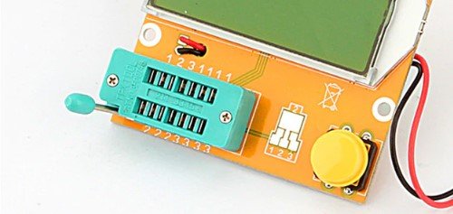
Now let's talk about how to check the electronic component. There is a ZIF panel for connecting elements. This is a special panel with a lever clamp for connecting electronic components. It is used most often on programmers and, as in our case, universal component testers.
Despite the fact that there are many connectors in the panel of the transistor tester, you can see in the photo above that the numbers from 1 to 3 are marked and they are repeated. The connectors are simply closed to each other, this is necessary for the convenience of connecting elements in different cases.
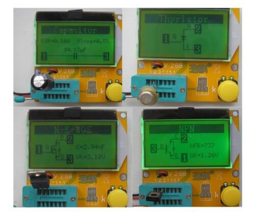
After connecting the element to the tester, you need to click on the button (or on the encoder, in the case of using the M328 model). A graphic designation of the component will be displayed on the screen, with its pinout and its characteristics (in the case of determining the parameters and serviceability). If the part is defective, it will produce something like “No, unkown, damage part”. The measurement takes a delay of 1-2 seconds, since the device first performs a self-test.
What measures and determines
The transistor tester can determine the parameters and the pinout of such semiconductor elements as:
- Two-output components - diodes, zener diodes, LEDs (shows the voltage at which the glow starts) and some others.
- Triodes - transistors (mosfet - gate capacitance and opening voltage, J-fet, bipolar - voltage drop and hFE), thyristors and triacs. It also checks the assembly of Schottky diodes in three-pin TO-220 cases and the like.
Passive components:
- resistors (measures resistance);
- capacitors (capacity, Vloss - voltage drop after a charging pulse, ESR);
- chokes and inductors (inductance, DC resistance).
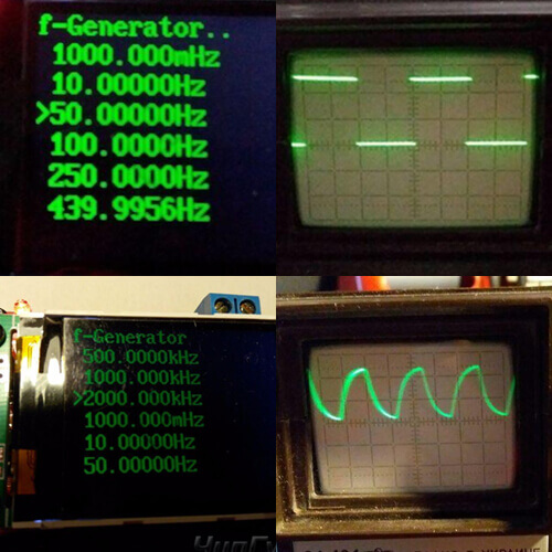
Models like GM328a have a built-in PWM signal generator with a pulse frequency of 8 kHz (it may also differ in different models), a frequency measurement function up to 2 MHz (it measures quite accurately the frequency of different signals - a sinusoid, meander, triangle, saw, there is also information about the fact that some versions "measure" up to 3.95 MHz), the function of a voltmeter (up to 50 V and often with large errors). The square wave generator function will also be useful - the transistor tester is capable of delivering a signal with a frequency of up to 2 MHz.
Please note that the lowest frequency - 1 Hz is denoted as 1000 MHz (m - small), that is, “millihertz”. This is not gigahertz!
Nuances
When using, remember the nuances and limitations of most transistor testers:
- Powerful thyristors can recognize as faulty or as transistors.
- Zener diodes. Determines how diodes are. The manufacturer claims normal recognition of elements with a stabilization voltage of less than 4.5V.
- Microchips and three-legged integral stabilizers (7805, 7905 and the like) are not detected and not verified.
- Dinistors do not check, because of their high response voltage, for example, the common DB3 has more than 30 volts.
- Large capacitors also do not recognize, although the manufacturer claims the measurement limits from 30 pF to 100 mF, "adequate" values are issued up to a couple of thousand microfarads.
- Inductance is measured in the range from 0.01 mg to 20 g.
- Ionistor does not recognize.
- Varistors sees as capacitors.
- Unidirectional suppressors defines as diodes.
- No input protection. This means that you can burn the input if you start to measure a charged capacitor, for example, or apply a high voltage. Therefore discharge the capacitors.
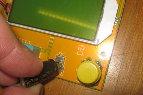
If you want to test a component, but it has short legs, then on the LCR-T4 tester you can make a test by attaching them to the site under the SMD.
In general, the device has found wide application and will be especially useful for beginner radio amateurs when buying the first equipment for a home laboratory. If you take into account the cost of the device, then with all its errors and shortcomings, you can put up even for the sake of the convenient function of determining the pinout and determining the ESR of electrolytes in the diagnosis of power supplies.
Now you know what a transistor tester is, how to use it and what this device is intended for. If you have questions, ask them in the comments under the article!
Related materials:

