Lighting control circuits through contactors and magnetic starters
The basics
To turn on magnetic starters and contactors, push-button stations are used. These are devices in which there are 2 or 3 buttons such as “Start” and “STOP” or “Forward”, “Back” and “STOP”, there are other less common options. These buttons are a non-locking button with a normally-closed and normally open pair of contacts.

Starters and contactors - These are electromagnetic switching devices. In order for his power contacts to close, you need to apply voltage to the coil. It will attract the core (anchor) on which the contacts are fixed (design may vary). When you remove the voltage from the coil, the device will turn off and its power contacts open.

In addition to power, these devices have block contacts (usually several of their groups). They are not able to withstand heavy loads, but are intended to implement self-pickup schemes and indications. The fact is that if you simply apply voltage to the coil through the button post, the device will turn on, but when you release the button, it will immediately turn off. This is necessary, for example, in winches and other hoisting mechanisms, but not in chains that operate for a long time without stopping, like light and electric motors of ventilation systems.
To avoid this, we need a self-pickup circuit - a normally-open contact block is connected in parallel with the “START” buttons on the button post.
Typically, such switching devices are used to connect high-power electrical appliances to the network: heating elements, motors, or, as in our case, large lighting installations.
The connection diagram of the button post and its principle of operation
To connect a contactor or starter to control the light from two buttons (like any other system) we need:
- Button post.
- Contactor or starter with the number of power contacts (poles) equal to the number of phases.
- Three cores of wire.
The contactor is connected to the button station as follows:
- The voltage of the apparatus coil (usually 220 or 380) is determined.
- The phase is taken from the power contacts (if the coil is on 380 - we take two opposite phases, if 220 - phase and zero).
- Connect the phase wire to the normally-closed contacts of the STOP button.
- In series with the STOP button, the START button is connected.
- From a normally open pair of block contacts of a contactor or starter, lay two wires to the push-button station (from two contacts, respectively) and connect them to the “START”, so that its normally open pair and open block contacts are connected in parallel. In this case, the contacts to which the phase has now arrived will be called conditionally “1”, and to which the phase will go after pressing a key and triggering the block contacts “2”. Important note: to this step we already have the incoming phase through the normally-closed "STOP" to the open "START", the contact blocks of the starter or contactor are connected to the same circuit.
- We connect the output of the coil to the block contact “2” (often on modern contactors they are designated as A1 and A2).

- We connect the second output of the coil to zero if it is designed for voltage 220V or to another phase - if it is 380V, respectively.
- We connect the power supply wires, from the same terminals they usually take the phase to the push-button post.
- Connect the wires from the lighting system (lighting systems themselves).
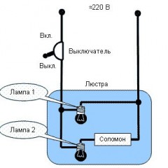
All that is described above, but in graphical form you can see in this diagram.

In the figure, the inclusion indication is additionally installed - a light bulb in the chain of control buttons and block contacts. It will allow you to understand whether the contactor and the external light are on, without departing from the button post.
Note: the light control circuit with the help of starters is also good in that you can easily organize light control from two or more places - you just need to add button posts in parallel with the existing ones.

Additional sensors
As mentioned above, lighting control using contactors and starters is often used in conjunction with automation, such as a light sensor and a motion sensor. Typically, such devices contain a small relay or triac, but the maximum power of the connected active load is usually limited to 1-2 kW. And there is no need to talk about the load with electromagnetic ballasts. The contacts of such relays are not designed to power them. Such a load can include powerful lamps such as DNaT, DRL, MGL and others, which are actively used in street lamps and spotlights.
For this, the circuit for switching on the lighting with a contactor or starter using sensors differs from the circuit with a push-button post only in that instead of a push-button post, we connect the coil of the switching device with the contact of the sensor output signal. Below you see the connection diagram of the motion sensor and photorelay to the contactor on the example of a single-phase network:


The schemes can be combined by organizing the forced inclusion of lighting, for this, in parallel with the signal from the sensor, we set the toggle switch, which will feed the phase to the coil.


If you intend to use the sensors in their pure form, please note that they are not designed to operate with a signal voltage of 220V AC. Therefore, devices such as the photo relay family FR, which are so common in everyday life, contain a sensor power circuit, triggers, or other threshold elements, the circuitry of which we will not consider in this article! If you are interested in this topic - write in the comments and we will tell you in detail about it. We hope you understand how lighting is controlled through a contactor and a magnetic starter. As you can see, the scheme is not complicated, the main thing is to understand the features of its work.
Finally, we recommend watching a video that demonstrates the application of such a scheme in everyday life:
Surely you do not know: