We assemble the transformer at home
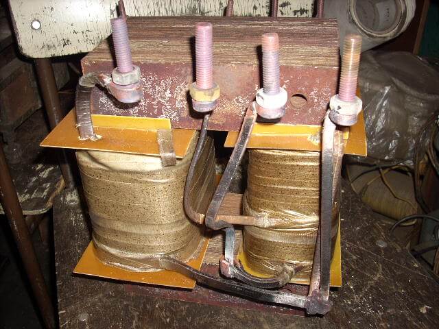
There are situations in life when you need a transformer with special characteristics for a particular case. For example, the network receiver in your favorite receiver burned out, and you have no such replacement. But there are other unnecessary vehicles from the old equipment that are lying around idle, so you can try to remake them yourself for specific parameters. Next, we will tell you how to calculate and make a transformer with your own hands at home, providing all the necessary calculation formulas and assembly instructions.
Settlement part
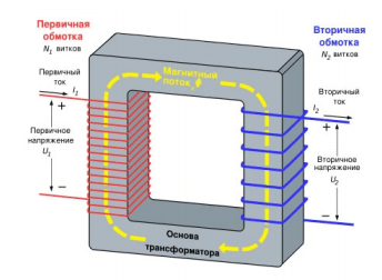
So, let's begin. First you need to figure out what such a device is. The transformer consists of two or more electric coils (primary and secondary) and a metal core made of separate iron plates. The primary winding creates a magnetic flux in the magnetic circuit, and that in turn induces an electric current in the second coil, as shown in the diagram below. Based on the ratio of the number of turns in the primary and secondary coils, the transformer either increases or decreases the voltage, and the current changes proportionally to it.
The maximum power that the transformer can give out depends on the size of the core, therefore, when designing, they are repelled from the availability of a suitable core. The calculation of all parameters begins with the determination of the overall power of the transformer and the load connected to it. Therefore, first we need to find the power of the secondary circuit. If the secondary coil is not one, then their power must be summed. The calculation formula will look like:
P2 = U2 * I2
Where:
- U2 is the voltage on the secondary winding;
- I2 is the secondary current.
Having obtained the value, it is necessary to calculate the primary winding, taking into account the loss of transformation, the estimated efficiency of about 80%.
P1 = P2 / 0.8 = 1.25 * P2
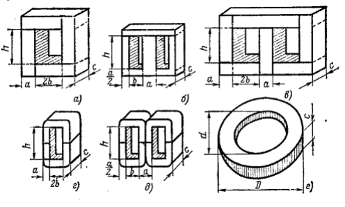
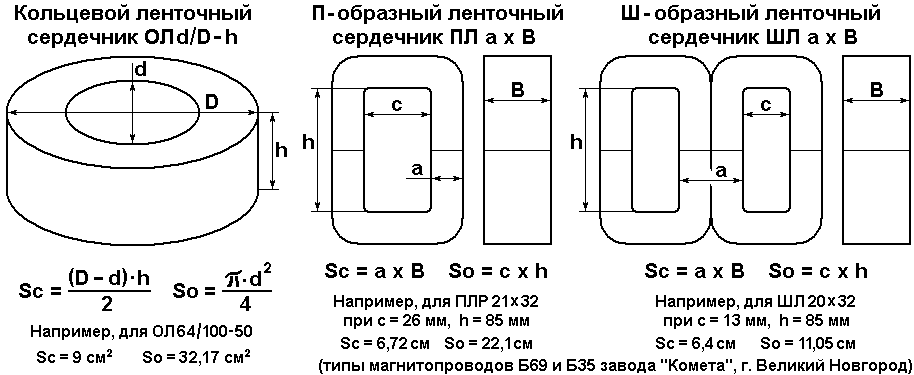
From the power value P1, a core is selected, its cross-sectional area S.
S = √ P1
Where:
- S in centimeters;
- P1 per watt.
Now we can find out the coefficient of effective energy transfer and transformation:
w ’= 50 / S
Where:
- 50 is the network frequency;
- S is the cross section of iron.
This formula gives an approximate value, but for ease of calculation it is quite suitable, since we manufacture the part at home. Next, you can start calculating the number of turns, you can do this according to the formula:
w1 = w ’* U1
w2 = w ’* U2
w3 = w ’* U3
Since the calculation is simplified and a small voltage drop under load is possible, increase the number of turns by 10% of the calculated value. Next, you need to correctly determine the current of our windings, you need to do this for each winding separately by this formula:
I1 = P1 / U1
We determine the diameter of the required wire according to the formula:
d = 0.8 * √I
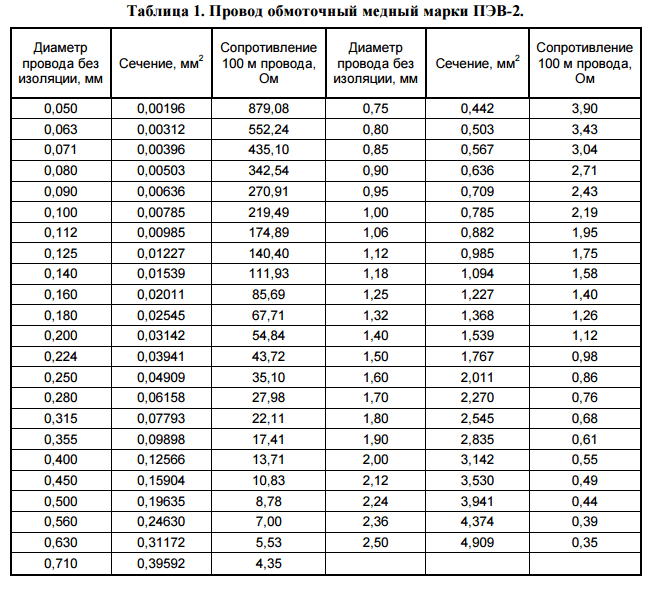
Based on table 1, select the wire with the desired cross section. If there is no suitable value, round up to the tabular diameter.
If the calculated diameter is not in the table, or if too much filling of the window is obtained, then you can take several wires of a smaller cross section and get the desired total.
To find out whether the coils fit on our homemade transformer, you need to calculate the window area of the receiver, this is the core-formed space in which the coils are placed. The already known number of turns is multiplied by the cross-section of the wire and the fill factor:
s = w * d² * 0.8
This calculation is performed for all windings, primary and secondary, after which it is necessary to summarize the area of the coils and make a comparison with the window area of the magnetic circuit. The core window should be larger than the coil sectional area.
Manufacturing procedure
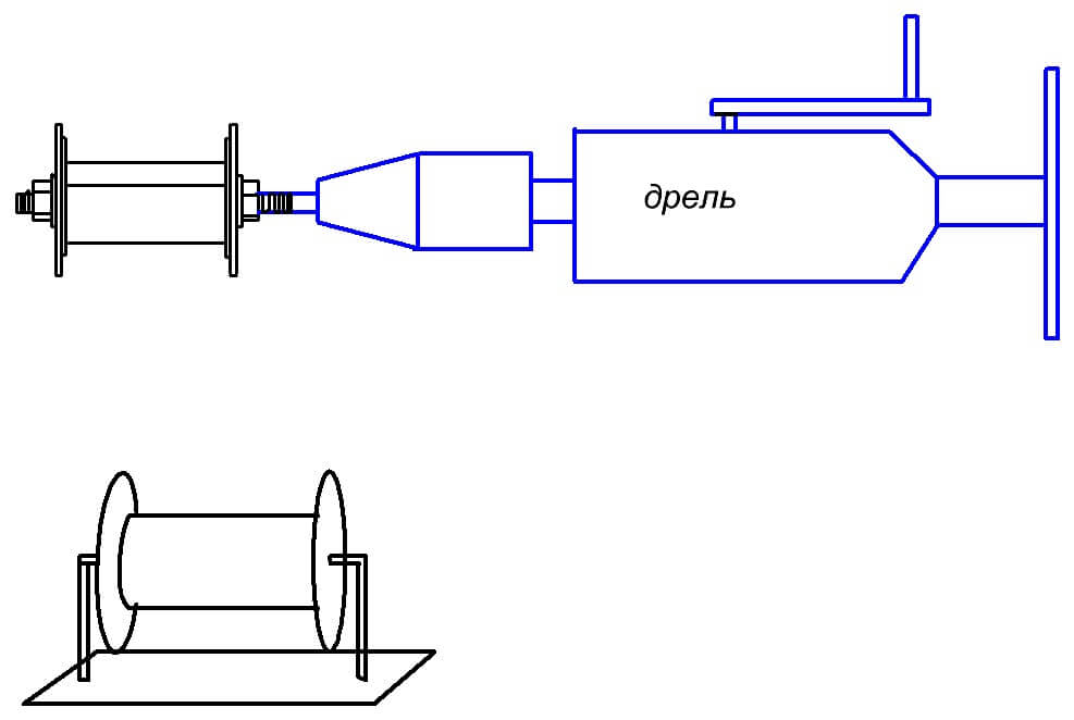
Now, having calculations and material for assembly, you can start winding. On the prepared cardboard coil, we lay the first layer of the winding. To do this, it is convenient to use an electric drill, holding the coil in the cartridge with the help of a special device (a bolt with two washers and a nut can act as it). Having fixed the drill on the table or workbench, at low speeds, we lay the wire, turn to turn without overlaps. Between the layers of wire we lay one layer of insulation - capacitor paper. Between the primary and secondary winding, two layers of insulation must be made to avoid breakdown.
It is much easier if you plan to rewind the finished transformer to the desired voltage. In this case, it is enough to count the number of turns of the secondary winding during unwinding, and knowing the transformation coefficient:
w ’= U2 / w2
You can calculate the required number of turns for the required voltage:
w2 = w ’* U2
We also recommend watching a video that clearly demonstrates the assembly order of the transformer at home:
Before testing, ring the windings, make sure that their resistance is not too small, there are no breaks and breakdowns on the product body. The first inclusion must be carried out with extreme caution, it is advisable to turn on an incandescent lamp with a power of 40-90 watts in series with the primary winding.
This article provides instructions that explain how to make a transformer with your own hands at home. For example, we described the sequence of calculation and assembly of the armored model, as the most common type of converters. Its popularity is due to the simplicity of the manufacture of winding units, the ease of assembly, repair and alteration. On the basis of this homemade product, you can easily make a tr-r for charging a car battery, or you can make a raising tr-r for a laboratory power source, an electric wood burner, a hot knife for cutting foam or another device for the needs of a home craftsman.
It will be interesting to read:

