Kirchhoff's First and Second Laws - Affordable Explanation
The first law of Kirchhoff
The definition of the first law is: “"The algebraic sum of currents flowing through a node is zero." You can say a little different form: "How many currents flowed into the node, the same number flowed out, which indicates the constancy of current ”.

A node of a chain is a connection point of three or more branches. The currents in this case are distributed in proportion to the resistance of each branch.
I1= I2+ I3
This form of recording is valid for DC circuits. If you use the first Kirchhoff law for an alternating current circuit, then instantaneous voltage values are used, are denoted by the letter İ and written in complex form, and the calculation method remains the same:

The complex form takes into account both the active and reactive components.
Second Law of Kirchhoff
If the first describes the distribution of currents in the branches, then the second Kirchhoff law is: “The sum of the voltage drops in the circuit is equal to the sum of all EMFs. ”In simple words, the wording reads as follows: “EMF applied to a section of a circuit will be distributed among the elements of this circuit in proportion to the resistances, i.e. according to Ohm’s law. "

Whereas for alternating current it sounds like this: "The sum of the amplitudes of the complex EMF is equal to the sum of the complex voltage drops on the elements ".

Z is the impedance or complex resistance, it includes both the resistive part and the reactive (inductance and capacitance), which depends on the frequency of the alternating current (in direct current there is only active resistance). Below are the formulas of the complex resistance of the capacitor and inductance:

Here is a picture illustrating the above:

Then:

Calculation methods for the first and second laws of Kirchhoff
Let's get to putting theoretical material into practice. To correctly place signs in the equations, you need to choose the direction of the circuit. Take a look at the diagram:

We suggest choosing a clockwise direction and mark it in the figure:

The dashed-dotted line indicates how to follow the path when making equations.
The next step is to compose equations according to the laws of Kirchhoff. First we use the second.We put the signs like this: a minus sign is placed in front of the electromotive force if it is directed counterclockwise (the direction we chose in the previous step), then for the clockwise emf we put a minus sign. We compose for each circuit, taking into account the signs.
For the first, we look at the direction of the EMF, it coincides with the dash-dotted line, set E1 plus E2:
![]()
For the second:
![]()
For the third:
![]()
The signs for IR (voltage) depend on the direction of the loop currents. Here the sign rule is the same as in the previous case.
IR is written with a positive sign if the current flows in the direction of the circuit bypass direction. And with a “-” sign, if the current flows against the direction of the circuit.
The direction of circuit traversal is a conditional quantity. It is needed only for the arrangement of signs in equations, it is chosen arbitrarily and does not affect the correctness of calculations. In some cases, a poorly chosen bypass direction can complicate the calculation, but this is not critical.
Consider another circuit:

There are as many as four sources of EMF, but the calculation procedure is the same, first we choose the direction for making the equations.

Now you need to make equations according to the first law of Kirchhoff. For the first node (figure 1 on the left of the diagram):
![]()
I3 flows in, and I1, I4 it follows, hence the signs. For the second:
![]()
For the third:
![]()
Question: "There are four nodes, but only three equations, why? ”The fact is that the number of equations of the first Kirchhoff rule is equal to:
Nequations= nknots-1
Those. there are only 1 less equations than nodes, because this is enough to describe the currents in all branches, I advise once again to go up to the circuit and check whether all the currents are written in the equations.
Now we proceed to the construction of equations by the second rule. For the primary circuit:
![]()
For the second circuit:
![]()
For the third circuit:
![]()
If we substitute the values of real voltages and resistances, then it turns out that the first and second laws are fair and are fulfilled. These are simple examples; in practice, much more voluminous problems have to be solved.
Conclusion. The main thing when calculating with the help of the first and second Kirchhoff laws is the observance of the rule for making equations, i.e. take into account the direction of current flow and circuit bypass for the correct arrangement of signs for each element of the circuit.
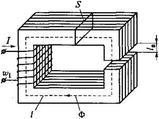
Kirchhoff's laws for the magnetic circuit
Calculations of magnetic circuits are also important in electrical engineering, both laws have found their application here. The essence remains the same, but the type and size change, let's look at this issue in more detail. First you need to deal with concepts.
Magnetomotive force (MDS) is determined by the product of the number of turns of the coil, by the current through it:
F = w * i
Magnetic voltage is the product of magnetic field strength and current through a section, measured in Amperes:
Um= H * I
Or magnetic flux through magnetic resistance:
Um= F * Rm

L is the average length of the plot, μr and μ0 - relative and absolute magnetic permeability.
Drawing an analogy, we write the first Kirchhoff law for a magnetic circuit:

That is, the sum of all magnetic fluxes through the node is zero. Have you noticed that sounds almost the same as for an electric circuit?
Then the second law of Kirchhoff sounds like “The sum of the MDS in the magnetic circuit is equal to the sum UM (magnetic stress).

Magnetic flux is equal to:

For an alternating magnetic field:

It depends only on the voltage across the winding, and not on the parameters of the magnetic circuit.
As an example, consider this contour:

Then for ABCD we get the following formula:
![]()
For circuits with an air gap, the following relationships are true:
Magnetic Resistance:

And the resistance of the air gap (on the right on the core):

Where S is the area of the core.
To fully understand the material and visually review some of the nuances of using the rules, we recommend that you familiarize yourself with the lectures that are provided on the video:
The discoveries of Gustav Kirchhoff made a significant contribution to the development of science, especially electrical engineering.With their help, it is quite simple to calculate any electrical or magnetic circuit, currents in it and voltages. We hope that now Kirchhoff’s rules for electric and magnetic circuits become more clear to you.
Related materials:


When we compose ur according to Kirchhoff’s 1 law, that is, a good explanation of the first ur. Why is there no explanation for the second and third, when everything is much more unobvious there? I2 clearly flows in there, but for some reason he has a positive sign
in the third equation, so generally all three I flow in. Why are they positive?
Please note that at the beginning of the article the equation is considered in the form I1 = I2 + I3, if you transfer everything to the left side of the equation, I1-I2-I3 = 0. The same thing was done there.
For the second node:
I1 = I5 + I2
moving everything in one direction will come out:
I1-I5-I2 = 0
Comparing with the direction of the circuit bypass, it becomes clear that it is better to change the signs, that is, multiply by minus 1.
Will come out
-I1 + I5 + I2 = 0
which is equivalent
I2 + I5-I1 = 0