Overview of the release of the maximum and minimum voltage RMM-47
What it is
RMM-47 is a overvoltage / undervoltage release. This is an optional device that works in conjunction with a load switch or circuit breaker. Its width is slightly less than 18 mm, which means that it occupies a space equal to one module in the shield.

Its technical characteristics:

The main thing we need to pay attention to is the response voltage characteristic:
- The minimum is 165 + -10% Volts.
- The maximum is 265 + -10% volts.
This means that the release will trip when one of these limits is reached with an error of 10%, while maintaining the protected circuit.
The RMM-47 trip unit does not have the ability to adjust the response threshold. All that is available to the user is the “RETURN” button to release the actuator and return the switching device to its original state.
The purpose of the release
RMM-47 is used to protect electrical installations from high and low voltage. Most often, such situations result from zero burn and phase imbalance in a three-phase network. This device does not protect against high-voltage impulses in the network. Its purpose is to monitor the parameters of the supply network and give a command to turn off the power to consumers.
Note: There are specialized devices for protection against impulse surges, for example, SPD - a variety of protective devices based varistors.
Depending on the connection scheme, using the maximum and minimum voltage release RMM-47, you can organize the protection of both specific electrical appliances and the entire facility as a whole by connecting the release to the input circuit breaker.
Mounting Features
Unlike voltage relay the RMM-47 trip unit does not have its power contacts, therefore, the rated current is not indicated in the characteristics. It is a prefix or an additional device for circuit breakers and circuit breakers.
To do this, on the side of most circuit breakers there is a hole that provides the connection of additional devices. In the photo below you can see how to access it. To do this, turn the plug and remove it from the seat.

In the window you see a part of the cocking mechanism of the circuit breaker.On the left side of the RMM-47 there is a protruding pin for the mechanical connection of the trip unit with the drive of the power contacts of the automatic machines and load switches.

This determines the principle of operation of the RMM-47 trip unit:
- The electronic control board analyzes the current voltage in the network and compares the value with the settings set by the manufacturer.
- In case of deviation of more permissible norms, it sends a control signal to the solenoid, which in turn is mechanically connected to the drive to connect the circuit breaker.
- Accordingly, together with the operation of the release solenoid, the disconnector mechanically connected to it will be disconnected. To return the devices to their original state and apply energy, click on the “RETURN” button and turn on the check box of the circuit breaker.
The following video clearly demonstrates the principle of installing such prefixes for switching protective devices:
Recommended Wiring Diagram
RMM-47 is connected to the phase emerging from the circuit breaker, to which it is connected. Here is a picture in the official technical documentation for the product by IEK.

In practice, the connection scheme of the RMM-47 in a single-phase network is as follows:

The scheme for connecting to a three-phase network is almost the same:

Such a connection is due to the fact that, if you take the phase to the machine, the devices will still be protected, but the release coil may fail, which is proved by repeated experiments of specialists. The result is a similar picture:

When connected according to the above connection diagram, this will not happen, since the release circuit will also be de-energized.
Conclusion
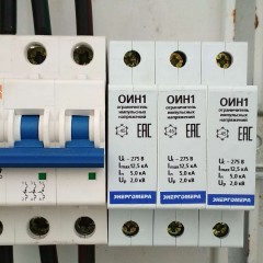
In addition to IEK, the RMM-47 trip unit is also produced by other manufacturers, for example, EKF has analogues in the PROxima line and TDM, whose products you can see below.

Such a device is not required for installation in each electrical panel, but is recommended. At the same time, if you are afraid for the state of your electrical appliances, install a voltage relay better. Their characteristics allow you to set the boundaries of the range of rated voltages, the upper and lower voltage operation. This will allow you to accurately adjust the device to the characteristics of the consumer and the local power supply network. In the considered release, the drawback may be precisely too wide a range of nominal values and the impossibility of regulating them. On the other hand, this simplifies the operation of the average user.
Finally, we recommend watching a video that clearly shows how to connect the undervoltage and undervoltage release:
This is where we end the review of the RMM-47. We hope that the provided description of the characteristics, the principle of operation and connection schemes helped you figure out what this unit is and whether it is needed in your dashboard.
Surely you do not know: