Design of synchronous voltage limiter
Anyone who has read previous posts about a fundamentally new overvoltage protection device - about synchronous limiter, and especially those who are familiar with switching power supplies of modern computer and other equipment, immediately thought, obviously, of the two main difficulties that are not so easy to overcome. This is a very high current pulse when the power is turned on, especially if several devices are connected to the ONS (and this, as a rule, is), and, secondly, heat dissipation on the ballast, in association with a conventional ballast resistor (from the experience of many), They are seen as such that cast doubt on the very idea of such a voltage limitation.
On the issue of heat, the developer has already given some explanations in the previous article, now he will supplement them with the following comments. If we look at a classic autotransformer, then it also has heat dissipation, and even such disadvantages (compared with ONS) as the weight and possible hum during operation. If we consider a modern stabilizer for 500 watts (the minimum power level), then according to the efficiency, which is an average of 97%, we can calculate the power dissipated by the transformer, and it turns out to be about 15 watts at rated load and most importantly at normal voltage (!) . In the ONS, on ballast, with such a load and a network voltage of about 255 V (the ONS begins to cut the amplitude starting from 245 in the effective voltage) according to the approximate calculation, which the author explained earlier (taking into account the duty cycle of the pulses - pieces of "excess amplitude"), will be stand out about 10 watts. He made this comparison only to dispel doubts about the rationality of using active ballast for synchronous voltage limitation. Of course, to compare the classical principle with the proposed one is for a specific place of application. After all, everything is determined by the network itself, its instability, the nature of the loads, constant and random, and the voltage requirements for consumers, other factors. Therefore, we further consider the issue of inrush current.
In the first prototypes, the developer used the KT818BM transistor for ballast, and he withstood the starting current of two TVs up to 100 watts of total power. Subsequently, the author began to use the Darlington transistor at 8-10 A in the TO-220 package (for small-sized cases), including with parallel connection. He did not set the goal of achieving maximum starting current, since there was a stage of testing the circuit on other issues, including the control of relay cutoff and cutoff by means of a controlled breaker (with a power button). By the end of last year, the developer managed to make a circuit with the relay returning to the working (disconnected) state when the voltage was reduced to normal. Such a limiter was introduced in a previous article. Then, the same case was added to the presented case, but already with a cooler and a current transformer (from which the cooler is powered) and temperature tests were carried out.They showed that the ONS, tentatively designed for 250 watts of load with frequent overvoltages up to 250-255 V, corresponds to this and can withstand (by heat) short-term overvoltages of this level and with a higher load power, up to 400-500 watts. I think many understand that the heating temperature of the radiator, and therefore the ultimate power released on the ballast (as part of the load power) is determined by the effective area of the radiator, cooler performance and ventilation characteristics of the limiter case itself. Therefore, the author does not provide here specific results of thermal tests (as is customary in the description of any product of this kind). We present only a graph illustrating the main characteristic of ONS for a load power of about 10 W:

For more power, you need a powerful input voltage regulator. But, there is absolutely no need to do this, since it should be clear to everyone that at high currents the regulation characteristic of the ballast transistor will be steeper, that is, the upper part of the graph will be more gentle.
But, back to the starting current. After the thermal tests, the developer, without any hesitation, turned on the netbook adapter through the ONS, which was distinguished by its “hard” start-up (which I remembered earlier by its strong sparking outlets) A subsequent ballast test (with a micro button) showed that the transistor (in TO-220) could not stand it. Measuring the current pulse with a special device showed a value of about 20 A (consider this in your practice!). Then the decision came to protect the transistor, and at the same time the relay contacts and the thermo-relay by a shunt triac (of the same version). The circuit is simple, between the cathode and the control electrode, a powerful resistor of the order of 0.47 Ohms is turned on. With a starting current that lasts about 5 ms, the triac will open and will pass most of the current through itself. But, the main thing is that this will ensure the reliability of the above contacts. The fact is that although the relay contacts are designed for 10-16 A, all relays have the ability to slowly "release" when the power is off, that is, the contacts will certainly spark (like a sparkling socket) and can even be welded to each other. The thermal relay contacts are even weaker in this respect - in the most convenient model they are designed for 5 A.
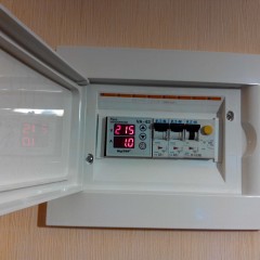
Thus, the ONS scheme has finally (presumably) been established in solving all the main features of its application. As already noted, the option with a miniature relay, which can now return to its original standby state, is the most complex in the circuit plan and has the significant drawback that the relay must be kept on for an indefinitely long time. Many people know that a case is likely. zero cliff and the appearance in the apartment network of a voltage of more than 300, or even all 380 volts (most likely, of course, in case of serious accidents and natural disasters in the area of your substation or on a long open line). Although the ONS relay circuit, by calculation, must withstand such an overvoltage, not allowing it to load, the thermal mode of the relay power elements will be quite stressful .. Therefore, the author of the development nevertheless leaned towards the option with a controlled breaker, briefly with a break relay ( relay - trip). The fact is that the circuit in this embodiment is simpler and does not have elements with a thermal load, and the break relay is controlled by a thyristor in the TO-92 package. The thermo-breaker itself has reliable contacts, which, thanks to the special design, open and close (through the external button) with high speed. This product is just created (by reputable companies) for reliable operation as a power line release. All of the above and the positive experience of refining the breaker to provide external control now inspired the developer to further improve this product, which is very convenient for the ONS, to create a full-fledged break relay, with control for switching off and on.Based on the results that are already seen as positive (from experience), the author will definitely make another message. Well, in conclusion, we provide some results that further illustrate the benefits of ONS. In terms of design, as can be seen below, the advantage is that it can be built into most of the existing buildings, that is, it makes little sense to make a special case (with attractive "things"). As shown earlier, ONS can be built into junction boxes, even for flush mounting. Let's start the illustration with the last kit tested, here it is:

In the lower compartment there is a cooler with a current transformer, a filtering capacitor (there may be varistors) and a shunt triac. This design is made only for testing and personal use in the future. For the general consumer, it should be of course different. For example, the upper nests should be excluded, as they are dangerous for children. Never do this in your creative workshops!
And here is a video showing the convenience of button tests, especially before handing over (selling) a product to a consumer:
And here is a video demonstrating the convenience of a “smooth” test in one of my first break relay designs:
Now look how it is possible to integrate ONS into the body of a 9-outlet filter-splitter manufactured by V.I.-TOK, for three separate outlets:

And even in such a case (strip radiators with transistors connected in parallel are located on the sides):

And here is how ONS can be arranged in a box under a double outlet, with a cooler 40x10 mm, for hidden installation in a non-combustible wall:

The developer did all the electronic boards, of course, with volumetric installation, without smd elements, therefore, with normal modern installation, the layout options will, of course, be even higher.
Well, now we share the incidental experience that will be useful to many. The developer uses the DT-838 multimeter, since it also measures the temperature using a low-inertia thermocouple, which is very convenient for testing it. So, even earlier, the switch often junk, then generally stopped turning off the device, although it measured normally. This forced to put a miniature slide switch in the power circuit. And just recently (in the heat of testing), the author of the development stuck a 220 V device, measuring a resistor at the limit of 2000 before that. He came to his senses in time using a run of numbers, but the resistance measurements disappeared. On other limits, nothing was disturbed (much to my surprise). After the autopsy, the destroyed smd resistor (R15) was found, crawled through the forums and recognized the approximate value - 1.5 k, found only 1.87 (precision), soldered it and then measured the same one - the deviation is less than 0.01. He checked all other limits and was even more surprised - what an amazing survivability (a term from the theory of reliability!). To your attention a visual example: