How does a capacitor motor work and why is it needed
Modern equipment uses slightly different types of electric motors. Different in design, characteristics and principle of operation, all these engines are selected for each specific case according to their parameters. At the same time, quite often electric motors with the ability to connect to a single-phase network are needed in instruments and equipment. One of the suitable options is a capacitor motor, the device and the principle of operation of which we will consider within the framework of this article.
Device and principle of operation
Speaking of capacitor induction motors, we will primarily talk about electric motors, originally designed to connect to a single-phase network. This has something in common with two-phase or three-phase motors, converted to connect to a conventional single-phase 220 volt network. But the significant difference between these electric motors is that here capacitor acts as an indispensable condition of the electrical circuit and the inclusion of such an induction motor in a three-phase 380 Volt network is simply impossible.
The device and principle of operation of a capacitor motor are based on physical properties induction motorbut, to create a driving force and rotation of the magnetic field, a starting capacitor is included in the winding circuit.
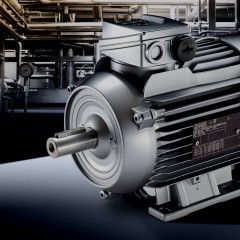
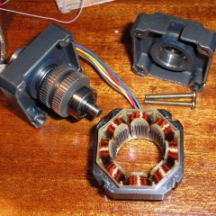
In its device, it does not differ from the usual asynchronous device and as a part has:
- Fixed stator in a massive case with working and starting windings.
- A rotor mounted on the shaft, driven by the force of the electromagnetic field created by the stator windings.
Both parts of the electric motor are interconnected on rolling or sliding bearings (bushings) fixed in the covers of the stator housing.
By the principle of operation, the capacitor motor, as noted above, refers to asynchronous - the movement is due to the creation of an electromagnetic field by the stator windings, 90 degrees shifted relative to each other. The only difference from three-phase asynchronous electric motors is the capacitor included in the circuit, through which the second winding of the electric motor is switched on.
 and capacitor (b)")
A conventional induction motor, when connected to the network, starts working with a starting winding. After the rotor has gained speed, the starting winding is switched off and only the working winding continues to work. The downside of such an electric motor with a starting winding is the start time, when the rotor begins to gain speed. It is important for the electric motor that at this moment there is no load, or the load is small. Starting torque is lower than that of three-phase motors with similar power.
In the connection scheme of a capacitor induction motor there is a phase-shifting capacitor.When connected to the network through a capacitor in the second winding, a phase shift of 90 degrees occurs (in practice, a little less). This contributes to the fact that the rotor is turned on with the highest possible torque.
")
Such a start ensures that the engine is turned on both at idle and under load. It is very important to connect the motor under load. In practice, according to this scheme, the motor is connected from the washing machine of the old models. At the time of starting, the engine should begin to rotate the water in the tank, and this is a significant load on the electric motor. In the absence of a starting capacitor, the engine will not start, it will hum, warm up, but will not work.
Types of capacitor motors
The connection scheme in which a capacitor induction motor is started only from the starting capacitor has one significant minus. During operation, the magnetic field does not remain circular or elliptical, performance decreases, and the electric motor heats up. In this case, for optimal operation, a working capacitor is included in the circuit, providing a constant phase shift, and not only at the time of start-up.
Note that two groups of capacitor motors can be distinguished:
- A capacitor is needed only for starting, then it is called starting. Usually these are low-power devices.
- A capacitor is needed for continuous operation, in which case it is called a worker. In high power machines (several kW), there may not be enough torque to start under load, and then an additional starting capacitor is connected. Most often this is done using the PNVS button.
More details on the connection diagram and how to distinguish these types of single-phase motors can be found in the following video clip:
In the international classification, the notation for the types of capacitor induction motors is used:
- motor starting via capacitor / winding operation (inductance) (CSIR);
- Capacitor Start / Capacitor Run (CSCR);
- Constant Separation Motor (PSC) engine.
 and with a working and starting (b)")
It is not hard to imagine how such a scheme works: a large-capacity starting capacitor provides engine starting, and after power is gained, a worker with a lower capacity provides the most suitable operating mode and rotor speed.

For special cases, when it is necessary to maintain the required rotor speed at different loads for working capacitors, different capacities are selected with the possibility of switching them.
To change the direction of rotation, in other words, turn on reverse, you need to swap the ends of one of the windings. For this, it is convenient to use a 6 pin toggle switch.

How to choose a capacitor for a starting capacitor
It should be said right away that on the nameplate of the engine, the capacitance of the starting and working capacitor (or only the working one, if the starting capacitor is not needed) is usually indicated. In this case, exact data specific to this particular electric motor with its features of the device and operation are indicated.

If the nameplate is jammed or missing, then it is possible to calculate the capacity of the working and starting capacitor for a single-phase rather than by the formula, but by the mnemonic rule:
The sum of the operating and starting capacitors should be 100 μF per 1 kW of power (70% starting and 30% working). If the motor is 1 kW, then a working capacitor is needed at 30 microfarads, and a starting capacitor is needed at 70. And the capacitors themselves must be designed for voltage more than in the mains. Usually choose about 400 volts.
But in the literature one can also find recommendations that the capacitance of the starting capacitor should be greater than the capacity of the worker by 2 times.

How to check the performance of the capacitor will tell you the article posted on our website earlier - https://my.electricianexp.com/en/kak-pravilno-proverit-rabotaet-li-kondensator.html
Field of practical application
Condenser induction motors are used in household electric fans, refrigerators, some modern washing machines, in almost all washing machines made in the USSR. But in hoods, motors with split poles without a capacitor are more often used, nevertheless, you can meet models with the type of electric motor in question.
In addition to household appliances, their scope also extends to pumps with a capacity of up to 2-3 kW, compressors and various machines with single-phase power, in general, to everything that should rotate and work from 220 Volts.
So we examined what a capacitor motor is, how it is designed and what it is for. We hope the information provided has helped you sort out the issue!
Related materials: