Why is reactive power compensation needed and how is it implemented
Definition
Full electrical power consists of active and reactive energy:
S = Q + P
Here Q is reactive, P is active.
Reactive power occurs in magnetic and electric fieldswhich are characteristic of inductive and capacitive loads when working in AC circuits. During active load operation, the phases of voltage and current are the same and coincide. When connecting an inductive load, the voltage lags behind the current, and when capacitive, it is ahead.

The cosine of the shear angle between these phases is called the power factor.
cos Φ = P / S
P = S * cos Φ
The cosine of the angle is always less than unity, respectively, the active power is always less than the total. Reactive current flows in the opposite direction relative to the active and prevents its passage. Since a full load current flows through the wires:
S = U * I
Even when developing power line projects, it is necessary to take into account the consumption of active and reactive energy. If the latter is too much, then you will have to increase the cross-section of the lines, which leads to additional costs. Therefore, they are struggling with it. Compensation of reactive power reduces the load on the network and saves the energy of industrial enterprises.
Where it is important to consider cosine phi
Let's see where and when reactive power compensation is needed. To do this, you need to analyze its sources.

An example of a primary reactive load is:
- electric motors collector and asynchronous, especially if in operating mode its load is small for a particular engine;
- electromechanical actuators (solenoids, valves, electromagnets);
- electromagnetic switching devices;
- transformers, especially at idle.
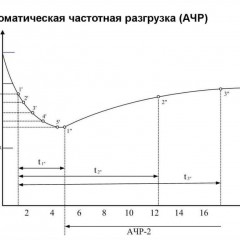
The graph shows the change in cos Φ of the electric motor when the load changes.

The basis of the electrical facilities of most industrial enterprises is an electric drive. Hence the high consumption of reactive power. Private consumers do not pay for its consumption, and enterprises pay. This causes additional costs, from 10 to 30% or more of the total amount of electricity bills.
Types of compensators and their principle of operation
In order to reduce the reagent, reactive power compensation devices are used, the so-called UKRM. As a power compensator, in practice they most often use:
- capacitor banks;
- synchronous motors.
Since the amount of reactive power can change over time, it means that the compensators can be:
- Non-regulated - usually a capacitor bank without the ability to disconnect individual capacitors to change capacitance.
- Automatic - compensation levels vary depending on the network status.
- Dynamic - compensate when the load quickly changes its nature.
The circuit uses, depending on the amount of reactive energy, from one to a whole battery of capacitors that can be inserted and removed from the circuit. Then management can be:
- manual (circuit breakers);
- semi-automatic (push-button posts with contactors);
- uncontrollable, then they are connected directly to the load, turn on and off with it.
Condenser batteries can be installed both in substations and directly near consumers, then the device is connected to their cables or power buses. In the latter case, they are usually calculated on the individual compensation of the reagent of a particular engine or other device - it is often found on equipment in electric networks of 0.4 kV.

Centralized compensation is carried out either at the boundary of the balance section of networks or at a substation, and can be done in high-voltage networks of 110 kV. The good thing is that it unloads the high-voltage lines, but the bad thing is that the 0.4 kV lines and the transformer itself are not unloaded. This method is cheaper than the rest. At the same time, the low side of 0.4 kV can also be unloaded centrally, then the UKRM is connected to the buses to which the secondary winding of the transformer is connected, and it is also unloaded.

There may also be a group compensation option. This is an intermediate form between centralized and individual.
Another way is compensation by synchronous motors, which can compensate for reactive power. It appears when the engine is in over-excitation mode. Such a solution is used in networks of 6 kV and 10 kV, and also occurs up to 1000V. The advantage of this method before installing capacitor banks is the ability to use a compensator to perform useful work (rotation of powerful compressors and pumps, for example).

The graph shows a U-shaped characteristic of a synchronous motor, which reflects the dependence of the stator current on the excitation current. Under it, you see what the cosine phi is equal to. When it is greater than zero, the engine is capacitive in nature, and when the cosine is less than zero, the load is capacitive and compensates for the reactive power of the rest of the inductive consumers.
Conclusion
To summarize, listing the main points about reactive energy compensation:
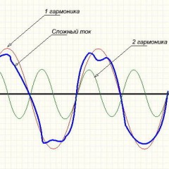
- Purpose - unloading power lines and electrical networks of enterprises. The device may include anti-resonant chokes to reduce the level network harmonics.
- Private individuals do not pay bills for it, but enterprises pay.
- The compensator includes capacitor banks or synchronous machines are used for the same purpose.
We also recommend watching useful videos on the topic of the article:
Related materials:


According to the book of V.E. Kitaev, L.S. Shlyapintokh "Electrical Engineering with Fundamentals of Industrial Electronics", paragraph 54 for the 1968 edition book and paragraph 53 for the 1973 graduation book, it is clearly written: ... "that in an AC circuit containing only inductance, current lags voltage... .. and ahead of EMF self-induction. We can say that in the inductive circuit, the voltage is 90 degrees ahead of phase in the current.
As for capacitive loading, the same book (the next paragraph No. 55 for the release of 1968 and No. 54 for the release of 1973) says: ...."when charging and discharging a capacitor …. The current is a quarter phase ahead of phase voltage, i.e. 90 degrees.
And you have written the opposite ...