How to check the health of the diode bridge - step by step instructions
What you need to know about diode bridges
To begin with, we will consider what are and what are inside the diode bridge. There are these elements of the circuit in two versions:
- From discrete (separate) diodes. Usually soldered on the board and connected by tracks to the correct circuit.

- Diode assemblies. Assemblies can be either single-phase bridges for rectification of both half-periods of alternating voltage, or assemblies of two diodes connected to a circuit by a common cathode or anode and other switching options.

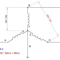
In any case, the rectifier single-phase diode bridge consists of four semiconductor diodes connected in series-parallel fashion. Alternating voltage is applied to two points at which the anode and cathode are connected (opposite poles of the diodes). DC voltage is removed from the connection points of the same poles: plus from the cathodes, minus from the anodes.
In the diagram, the location of the AC voltage connection is indicated by the symbols AC or “~”, and the outputs with constant voltage “+” and “-“. Draw this scheme for yourself, it will be useful to us when checking.

If you imagine a real diode bridge and combine it with this circuit, you get something like:

Location of the diode bridge on the board and precautions
Diode bridges are installed in power supplies of both pulse and transformer. It is worth noting that in the pulse blocks, which are now used in all household appliances, the bridge is installed at the input of 220V. At its output, the voltage reaches 310V - this is the amplitude voltage of the network. In transformer power supplies, they are installed in the secondary circuit, usually with low voltage.
If the device does not work and you find a blown fuse, do not rush to turn on the device after replacing it. Firstly, if there are problems on the board, the fuse will blow again. Such a power supply must be turned on through a light bulb.

To do this, take a cartridge and screw into it a 40-100 W incandescent lamp and connect it to the phase wire gap to connect to the network. If you are going to repair power supplies often, you can make an extension cord with a cartridge installed in the gap of the power cable to connect the lamp, this will help save your time.

If there is a board short circuit - when connected to the network, a high current will flow through it, the fuse or circuit on the circuit board, or wire, will blow out, or the machine will be knocked out. But if we inserted a light bulb into the gap, the resistance of the spiral of which limits the current, it will light up in full heat, preserving the integrity of all of the above.
If there is no short circuit or the unit is serviceable, either a slight glow of the lamp or its complete absence is permissible.
The simplest and coarsest check
We will need an indicator screwdriver. It costs a penny and should be in the toolbox in every home. You just need to first touch the input of the rectifier 220V, if the indicator lights up on the phase wire, then the voltage is present, if not, the problem is clearly not in the diode bridge and you need to check the cable. If there is voltage at the input, we check the voltage at the positive output of the rectifier, it can reach 310 V at this point, the indicator will show it to you. If the indicator does not light, the diode bridge is open.
Unfortunately, we won’t be able to find out anything else with an indicator screwdriver. About, how to use an indicator screwdriver, you can find out from our article.
Diode bridge diode multimeter
Any part on the board can be pulled out for verification or ringing without soldering. However, the accuracy of the check in this case is reduced, because perhaps the lack of contact with the board tracks, with visible "normal" soldering, the influence of other circuit elements. This also applies to the diode bridge, you can not solder it, but it is better and more convenient to solder it for checking. The bridge, assembled from separate diodes, is quite convenient to check on the board.

Almost every modern multimeter has a diode test mode, usually it is combined with the sound of the circuit.

In this mode, the voltage drop in millivolts between the probes is output. If the red probe is connected to the anode of the diode, and black to the cathode, this connection is called forward or conductive. In this case, the voltage drop at the PN junction of the silicon diode lies in the range of 500-750 mV, which you can see in the picture. By the way, it shows a test in the resistance measurement mode, it is also possible, but there is a special mode for checking diodes, the results will, in principle, be similar.

If you swap the probes in places - red to the cathode, and black to the anode, the screen will either have a unit or a value greater than 1000 (about 1500). Such measurements indicate that the diode is serviceable, if in one of the measurement directions they differ, then the diode is faulty. For example, a continuity tripped - the diode is broken, in both directions high values (as when turning it back on) - the diode is cut off.
Important! Schottky diodes have a smaller voltage drop, of the order of 300 mV.
There is also an express check of the diode bridge with a multimeter. The procedure is as follows:
- We put the probes at the input of the diode bridge (~ or AC), if the pro-ring works, it is broken.
- We put the red probe on “-”, and the red probe on “+” - about 1000 is displayed on the screen, we change the probes in places - on the screen 1 or 0L, or another high value - the diode bridge is working. The logic of such a check is that the diodes are connected in series in two branches, pay attention to the circuit, and they conduct current. If the plus power is applied to - (the connection point of the anodes), and the minus the power to “+” (the connection point of the cathodes), this happens when the phone rings. If one of the diodes is open, the current can flow along the other branch and you can make erroneous measurements. But if one of the diodes is broken, the voltage drop on one diode will be displayed on the screen.
The video below clearly shows how to check the diode bridge with a multimeter:
Full diode bridge test
You can also check the diode bridge with a multimeter according to the following instructions:
- We set the red probe to “-”, and in black touch the terminals to which the alternating voltage “~” is connected, in both cases there should be about 500 on the screen of the device.
- We put the black probe on “-”, touch the terminals “~ or AC” in red, one on the multimeter screen, which means that the diodes do not conduct in the opposite direction. The first half of the diode bridge is operational.
- The black probe is on “+”, and the red touch the AC voltage inputs, the results should be as in 1 point.
- We change the probes in places, repeat the measurements, the results should be as in paragraph 2.
The same can be done with a “tseshka” (a universal measuring device of Soviet manufacture). How to check the diode bridge with a pointer multimeter, described in the video:
By the way, the test can be performed without a tester at all - with a battery and control light (or LED). When the diode is turned on correctly, current will flow through the bulb and it will light up.

In conclusion, I would like to note that diode bridges are installed everywhere: in the charger, welding machine, on the inverter, in power supplies, etc. Thanks to the described technique, you can check the diodes for operability at home.
It will be useful to read:


Klas !!!