How to reverse a direct and alternating current electric motor
Reversing DC Motors
The easiest way is to reverse the DC motor, which has a stator with permanent magnets. It is enough to change the polarity of the power supply so that the rotor starts to rotate in the opposite direction.
It is more difficult to reverse the motor with electromagnetic excitation (serial, parallel). If you simply change the polarity of the supply voltage, the direction of rotation of the rotor will not change. To change the direction of rotation, it is enough to change the polarity only in the field winding or only on the rotor brushes.
To reverse the high power engines, the polarity should be changed at anchor. A rupture of the field winding on a running motor can cause a malfunction, because the resulting EMF has an increased voltage, which can damage the insulation of the windings. Which will lead to the failure of the electric motor.
To implement the reverse direction of rotation of the rotor, bridge circuits are used on relays, contactors or transistors. In the latter case, it is possible to adjust the rotation speed.

The figure shows a transistor circuit. By way of illustration, the transistors are replaced by switch contacts. Similarly, bridge circuits are performed not on bipolar, but on field-effect transistors.

The efficiency of such a circuit is much higher than on transistors. The control is carried out by a microcontroller or simple logic circuits that prevent the simultaneous supply of signals.
Changing the direction of rotation of the rotor of an induction motor
The most widespread in industry induction motorspowered by a three-phase voltage of 380 volts. In order to reverse, just change any two phases.
A wiring diagram made on two magnetic starters gained distribution. Actually for DC motors, it is similar, but bipolar contactors or starters. This circuit is called the “reversing starter circuit” or “the reversing starting circuit of an asynchronous three-phase electric motor”.

When the KM1 starter is turned on by the “Start 1” button, voltage is directly applied to the windings and the “Start 2” button is blocked from being accidentally turned on by opening normally-closed contacts of the KM-1. The engine rotates in one direction.
After disconnecting the KM1 starter with the Stop button or by completely removing the voltage, you can turn on the KM2 with the Start 2 button. As a result, through the contacts, the L2 line is supplied directly, and L1 and L3 are interchanged. The “Start 1” button is locked, since the normally-closed contacts of the KM2 starter are driven and opened. The engine starts to rotate in the opposite direction.
The scheme is used everywhere to this day to connect a three-phase motor in a three-phase network. The simplicity of the circuit solution and the availability of components are its significant advantages.
Most common are electronic control systems. Switching circuits, which are assembled on thyristors without starters. Although starters can be installed to remotely turn on or off in this circuit.

They are more complicated, but also more reliable than devices on contactors. For control, pulse-phase control systems (SIFU), frequency control systems are used. These are multifunctional devices, with their help it is possible not only to reverse an asynchronous electric motor, but also to regulate the rotation frequency.
At home, there is a need to connect a 380V to 220 engine with reverse. To do this, you need to switch the star triangle windings. In more detail, we examined the differences between these schemes in an article posted on the site earlier: https://my.electricianexp.com/en/chto-takoe-zvezda-i-treugolnik-v-elektrodvigatele.html.
However, if intended connection of a three-phase electric motor to a single-phase network, then a capacitor is used for this, which is connected according to the scheme below.
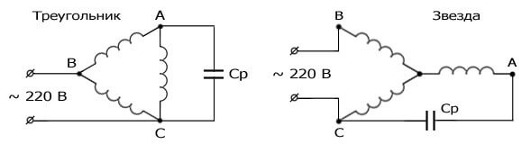
In this case, in order to reverse, it is enough to switch the network wire from B to terminal A, and disconnect the capacitor from A and connect to terminal B. It is convenient to do this using a 6-pin toggle switch. This is a typical inclusion of an induction motor to a 220V network with a capacitor.
Wiring diagram for a reversible commutator motor
To reverse the collector motor, you need to know:
- Not on everyone collector motor can reverse. If the rotation arrow is indicated on the case, then it cannot be used in reversing devices.
- All engines with high revolutions are designed to rotate in one direction. For example, an electric motor installed in grinders.
- In an engine that has low revolutions, rotation can be carried out in different directions. Such motors are mounted in power tools, for example, electric drills, screwdrivers, washing machines, etc.
The figure shows a diagram of a universal commutator motor, which can operate both from direct and alternating current.

To change the rotation of the rotor, it is enough to change the polarity of the voltage across the winding rotor or stator, as in DC motors, from which universal machines practically do not differ.
If you simply change the polarity of the supply voltage on the collector motor, the direction of rotation of the rotor will not change. This must be taken into account when connecting the electric motor to the network.
You should also know that in high power motors, the armature winding commutes. When switching the stator windings, voltage appears self-induction, which reaches values that can disable the engine.
Amateur designers in their crafts use various engine types. Often they use a brush motor from a washing machine.These are convenient motors that can be connected directly to a 220 volt network. They do not require additional capacitors, and the speed control can be easily done using a standard dimmer. Six or seven pins are output to the terminal block.
Depends on engine type:
- Two go to the collector brushes.
- A pair of wires comes from the tachometer to the block.
- Field windings can have two or three wires. The third serves to change the speed of rotation.

To reverse the motor from the washing machine, it is necessary to interchange the outputs of the field winding. If there is a third conclusion, then it is not used.
Arduino electric motor reverse circuit
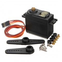
In the design of models or robotics, small DC brush motors are often used, which are controlled by a programmable arduino microcontroller.
If the rotation of the engine is assumed only in one direction, and the electric motor power is small, and the supply voltage is from 3.3 to 5 volts, then the circuit can be simplified and powered directly from the arduino, but this is rarely done.
In models with remote control, where it is necessary to use reverse motors with a voltage of more than 5V, apply keys assembled according to the bridge circuit. In this case, the connection diagram of the engine with reverse to arduino will look similar to that shown below. This inclusion is most often used.

In the bridge circuit, field-effect transistors or a special matching device can be used - a driver with which powerful motors are connected.
In conclusion, we note that a trained specialist must assemble the reverse circuit of the electric motor. However, when self-connecting, it is necessary to comply with safety conditions, select the appropriate connection diagram and select the necessary accessories, strictly following the installation instructions. In this case, the designer will not have difficulties in connecting and operating the electric motor.
Now you know what the reverse of the electric motor is and what connection schemes are used for this. We hope the information provided was useful and interesting for you!
Related materials: