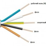
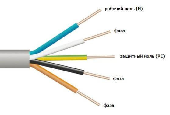
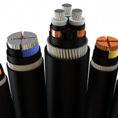
Wire color coding

If you incorrectly connect the contacts to each other in color, this can cause adverse effects such as electric shock and short circuit.
The main purpose of color marking is to create safe conditions for electrical work, as well as reducing the time for searching and connecting contacts. Today, according to the PUE and existing European standards, each core has its own isolation color. About what color the wire phase, zero, earth, we will talk further!
What does grounding look like?
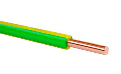
According to the PUE, the insulation of the "earth" should be painted in a yellow-green shade. We draw your attention to the fact that the manufacturer also applies the application of yellow-green stripes to the ground wire in the transverse and longitudinal directions. In some cases, the shell may be pure yellow or pure green. On the electrical circuit, grounding is usually denoted by Latin letters "PE". Very often, “land” is called zero protection, do not confuse it with zero working (zero)!
-
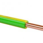
- Appearance
-

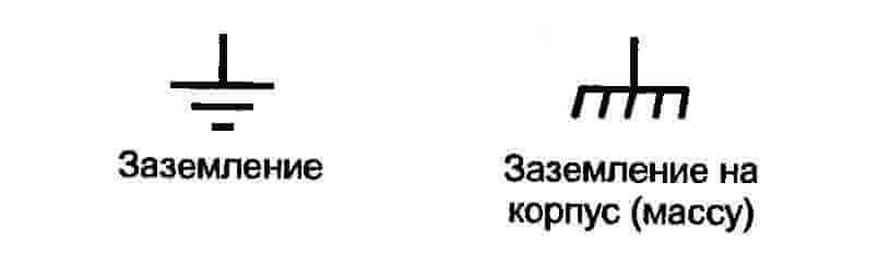
- Graphic image on the diagram
What does neutral look like?
In three-phase and single-phase mains, the color of zero should be blue or blue. On the electrical circuit, "0" is usually denoted by the Latin letter "N". Zero is also called a neutral or zero working contact!
-
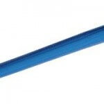
- Standard color

-
- Indication of neutral on the wiring diagram
What does the phase look like?
The marking of the phase wire (L) by the manufacturer can be carried out in one of these colors:
- the black;
- white;
- Gray;
- red;
- brown;
- Orange;
- Violet;
- pink;
- turquoise.
Most often, the color of the phase wire is brown, black and white.
-
- Shell color
-
- Electric circuit
It's important to know!
The color marking of wires in an electrician has many features and often beginners come across issues such as:
- "What is the abbreviation PEN?";
- “How to find grounding, phase, zero, if the insulation is colorless or has a non-standard color?”;
- "How to independently indicate the phase, grounding, zero?";
- “What other insulation standards exist?”
We will briefly give a simple explanation for all these questions!
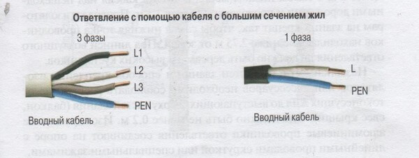
What is a PEN?
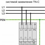
The outdated TN-C grounding system today involves the use of a combination of neutral and grounding. The advantage of such a system is the ease of electrical work. The disadvantage is the risk of electric shock when installation of electrical wiring in the house or apartment.
The color of the combined wire is yellow-green (like PE), but at the same time the insulation at the ends has a blue color, characteristic of neutral.On the electrical diagram, the combined contact is indicated by three Latin letters - "PEN".
-
- PEN indication on the wiring diagram

-
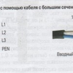
- Combination options for various types of power supply
How to find L, N, PE?
So, you are faced with this situation: during the repair of the household electrical network, it turned out that all the conductors are the same color. How in this case to find out which wire means what?
If a single-phase network is presented without a “ground” (2 cores), then all you need is a special indicator screwdriver. With its help, you can easily determine where 0 and where phase. About, how to use an indicator screwdriver we told. First, turn off the electricity on the shield. Next, we clean the two conductors and separate them from each other. After that, turn on the electricity supply and carefully determine the phase / zero using the indicator. If a light comes on when it comes into contact with a wire, this is a phase, so the second wire is zero.
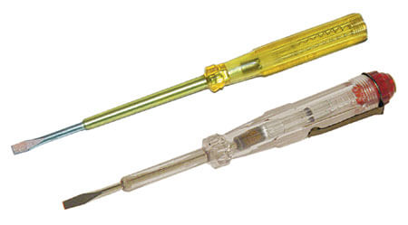
Indicator screwdriver
In the event that the wiring has a grounding wire, you must use equipment such as a multimeter. This device has two tentacles. First you need to set the AC current measurement range to over 220 volts. Next, we fix one tentacle on the phase contact, and using the second tentacle we determine zero / ground. In contact with 0, the multimeter displays a voltage value within 220 volts. If you touch the "earth" - the voltage will certainly be slightly lower. More intelligiblemultimeter instructions was provided in the corresponding article, which we recommend that you read!
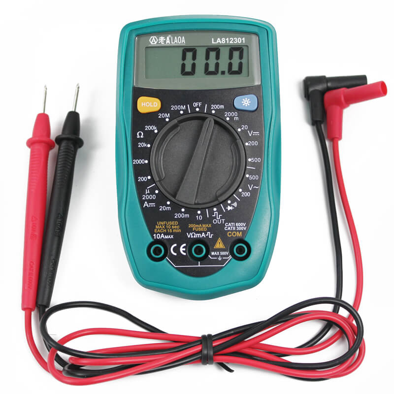
Multimeter
There is another method of determination. If there is no multimeter and indicator screwdriver at hand, then you can try to determine what color the wires L and N are by their insulation. In this case, you must remember that the blue shell is always ZERO. In any non-standard marking, the color of zero does not change. The other two cores will be a little more difficult to determine.
The first version of the associations. You see the remaining color, black or white contact. In the good old days, the earth was designated black or white insulation. It is quite reasonable to assume that it is she, the remaining color - phase (L).
The second option. Zero, again, immediately fold back, there is a red and black / white wire. If the insulation is white, then according to the PUE it is a phase. So the remaining red is the earth.
We draw your attention to the fact that such a method is extremely dangerous. If you decide to use it, be sure to make notes for yourself so that during chandelier repair or sockets do not get an electric shock!
I would also like to note a very important nuance - in a direct current circuit color marking of plus and minus is represented by black (-) and red (+) insulation color. As for the three-phase network (for example, on transformers), here all three phases have their own individual colors: phase A - yellow, B - green, C - red. Zero, as usual, is blue, and grounding is yellow-green. In the 380 V cable, wire A is white, B is black, C is red. Zero working and protective conductors do not differ from the previous color marking option.
How to specify L, N, PE independently?
In the event that the visual designation is missing or differs from the standard, it is recommended to independently indicate all the elements after repair work. To do this, you can use colored tape or a special product - a heat shrink tube, also called cambric. According to the requirements of the PUE, GOST and generally accepted recommendations, the wires must be indicated at the ends of the conductor - at the places of its connection with the bus (as shown in the photo).
-

- Multicolored cambric

-

- Shrink tube designation

Small color marks will facilitate the repair and maintenance of both you and the electrician, who will be able to carry out repairs of the home electrical network after you! About, how to mark wires in the shield, we told in a separate article.
Existing Factory Standards
The designations of insulation change slightly with each decade, so this information may be useful to you.
Until the year 2000, the following color coding of wires was used:
- white - N;
- black - PE;
- bright - L.
A few years after this standard, a significant change was made: PE was “repainted” in yellow-green (as it is now).
Thus, the products began to look like this:
- yellow-green wire - ground;
- black (and sometimes white) - neutral (N);
- bright is the phase.
Color schemes
If for some reason you get confused between the contacts, we offer you a detailed decoding of the marking of wires and cables by colors, which today complies with European and domestic standards:

Finally, we recommend watching a useful video on the topic:
Similar materials:


I bought a float level controller, there are three wires Black. Brown and Blue, which one is phase, earth and zero?
Hello! Write in detail the make and model of the regulator!
Black- Earth
Brown - Phase
Blue - Zero
So I bought a 3 * 1.5 wire
black brown, blue, it is necessary to connect the socket, with grounding and what to do?
Well, it's easier here! Just sign for yourself each wire on both sides (from the connection side in the junction box and from the outlet). I would recommend that you make the blue wire zero, the brown phase, and the black ground!
Black phase blue 0 cor earth
In fact, you just need to adhere to GOST R 50462-2009, which determines that
yellow green is PE,
blue is neutral
blue with yellow-green at the ends or vice versa - PEN
brown - L / L1,
black - L2,
gray - L3.
Yellow and green colors are prohibited due to the similarities with yellow-green. If any of these colors are present, if possible, use them only for PE.
Accordingly, all other colors can be anything. The article says that white is a phase, nothing of the kind. For white, as the most used in the manufacture of wires (the cheapest option), there is no specific match for any conductor.
The worst option is when you have to set any color in violation of GOST, for example, when such colors lived: black, brown, blue. According to GOST, do brown - L, blue - N. The remaining black do PE. Grounding will at least be similar to the Soviet standard (black), but will violate GOST, where black is a phase, nothing can be done. Please note that there is an international standard according to which black is L / L1 and brown is L2. Sometimes they demand to observe it. So if you do an electrician not at home, but somewhere at the facility, an incident may happen, so it’s better to clarify this issue right away.
Another bad option is when the remaining color is not associated with the conductor. For example: red, blue, black. According to GOST, blue is neutral, black is phase, red is not defined. Accordingly, assign red color PE. In this case, it is better to stock up on the yellow-green electrical tape and, if possible, mark the red wire with it, because the only thing associated with red is the phase. In no case do red - phase, and black - PE (although this suggests itself, right?). In this case, you violate the GOST, and if someone is shocked by the current, then you will not be covered by the GOST.
As for the choice of colors not indicated in the GOST, we can only recommend the following:
If the conductor does not have black, brown or gray, but there is red, then it must be made a phase, it is associated with the phase and is more or less close to the brown set by GOST.
If the conductor does not have blue, but there is white, then make it neutral. You will not violate GOST, but such a standard exists in many countries (in the USA, for example). This is especially true against the background of the fact that we have a very common two-core cable with white and black wires inside.
And I forgot to say. No matter how you sometimes have to violate GOST in hopeless situations, never put a phase on the yellow-green conductor. For example, there are such wires: brown, black, blue, yellow-green, on which it is necessary to put three phases and a neutral. In this case, the neutral must be planted in yellow-green, and the third phase in blue with cambric or gray tape.
Hello everyone! I want to share an excellent video on the color marking of wires, in accordance with current standards.
https://www.youtube.com/watch?v=oB1ZfYCnhJg
Enjoy watching.
There is a two-wire wire. The shell is green. It has two wires - yellow and purple insulation with cores of 7 conductors with a diameter of 0.51 mm, i.e. section about 1,5mm2.
Conductors are not copper or steel (does not magnetize). Not aluminum. The color is silver. (specific gravity is about 8.4 Gy / mm3). Maybe someone met - what kind of wire?
Wire BU. In the violet insulation (it seems, the phase), the conductors turned black, but in yellow the color did not change (silver).
Good night! Black, red and white wires are coming out of my wall, please tell me what to connect to? If on the stove in the plug are connected: yellow-green - earth; brown phase; blue is zero. For earlier saved a bo!
As already written in this article, until 2000 they used wire marking by color as follows: white - zero;
black is earth, bright is phase. In your case, in theory, white should be combined with blue, black with yellow-green and brown with red. But it is better to additionally use a tester to determine where the phase is, where is the earth, and where is zero (on the wires that go from the wall).
Goodnight!
In the bathroom there is a box near the floor. There are two yellow-green wires twisted together. Both go to the ceiling in the wall. What is this conclusion and why? thank
the yellow-green wire is the ground. in the bathroom it is present to bind metal objects to it (bathtub, shelf, etc.). if something somehow closes on the object, then current will flow through the ground wire (yellow-green). Upon reaching a current strength of 30 μA, the RCD will be switched off (in the electrical panel) and will not kill a person. my answer is very simplified, but the essence, I think, is clear.
My personal opinion is that the bathtub and sink in the bathroom should not be grounded.
Imagine that you are washing in the shower while standing in the bathroom and at that time lightning has got into the water supply system somewhere, and some part of the electricity will pass through the water under which you stand in the shower.
Or, for example, take an accumulative boiler in which ten will leak. Part of the current will flow to the boiler body, well, something is not made of polymer and has grounding. Part will go through your body.
In the BATHROOM near the FLOOR, the distribution box, I’m already in jitters ...) Well, what has calmed me down is grounding). In rooms with low electrical safety - dampness, conductive floors or dust, etc., using powerful electric consumers - boilers, electric boilers, electric .plates, etc., MANDATORY! connecting a good ground loop. Moreover, by individual conductors of the corresponding section, and best of all, if possible, by a metal bus by welding. In the switchboards, the use of an RCD or a differential automat. The cut-off from the available ones is 30-10mA, which is very important, since a current of 100mA with an alternating voltage of 220V is considered life-threatening, respectively according to the PUE, in such places, protection of 10mA is selected cutoffs.
Good evening! Tell me please! I connect the engine from the air conditioner to a proofing cabinet (alterations) with the inscription 1 microfarad, 3 wires from the cabinet to the adapter with 4 holes, as you said - blue (n), brown (L), empty hole and yellow-green (PE ) And from the motor there are 3 wires: white, red and brown. I connected - white to (N), red to (L) where I already connected one end of the 2.5 microfarad capacitor, and brown connected to the empty hole and connected the second end of the capacitor. The result is a motor, as I understand it, heats up and sometimes does not turn on when it pleases. What to do and what is wrong I did? !! I really hope for help,
The capacitor is used to start the winding of the motor, rather. If there is a passport, there is usually an electrical connection diagram there. And so, just poke it) try changing the wire in turn to the second output of the capacitor. If the motor with a capacitor start has either two separate or two with a common output winding. You probably have the last option. Judging by how the motor drives, the working winding is more likely to get to the capacitor. To determine which winding on which terminals it is possible, the tester-working winding will always be less in ohmic resistance - turn it on directly to the line, and the one that shows more resistance through the capacitor.
In general, the color coding that was discussed above is for power circuits. For control or control circuits, it can be different or completely arbitrary, although yellow-green is always earth.
help out !! I try to charge, it does not work.
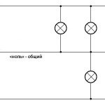
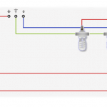
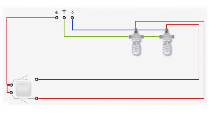
Good day . Tell me please. In the bathroom, one lamp is in one bundle with 4 ceiling lights. He took off the lamp and stepped as it was arranged hidden.
Help pliz
thank
Judging by the photo, you have organized the connection of lamps with a cable, i.e. the cable is routed across all the lamps that are connected in parallel. So, turn off the light, check the indicator for lack of voltage at the ends, connect the colors of the cable wires and to them, connect the lamp, isolate. The phase that you can find by the indicator should go to the middle contact of the cartridge (call the tester or visually). The indicator will show the presence of phase on one cable - this is the lead-in, on the cable going further down the cable, the indicator should not light up. If the wires are different in color, then determine the lead-in with the phase above and connect the outgoing one to it in parallel. Remember what color you connected the phase to.
In the photo it’s not entirely clear - two cables or three, or two cables and a separate wire. Perhaps you have 3 cables there, but everything else is as above, just connect all three in parallel, if all the lamps are 220V
Now dofiga, just almost all three-phase VVGng come with the color white, white-brown, white-black, white-blue, yellow-green. The stump is clear that white \ brown \ black is a phase. But what phase is coca color ?!
According to GOST, the color coding of a five-core cable means: yellow-green wire - earth, white-blue - zero, white-brown - phase A (L1), white-black - phase B (L2), white - phase C (L3). Information taken from GOST R 50462-2009.
But how then about the simplified BChK (white, black, brown) in the phase marking? The phase installers do in this order ..
I change the wire of an electric kettle, what color suits each other
Blue connect with blue wire, white with brown, yellow-green with green.
Good afternoon. I independently replace the old chandelier with a new five-arm metal. When connected, I encountered the same color marking of wires as Pavel and his teapot: the chandelier wires (as expected) are yellow-green, blue and brown, wiring is white, blue and dark green. The wiring is new, only 3 years as they changed. Did I understand correctly that the connection order will also be blue with blue (N), white with brown (L), and green with yellow-green (PE)?
Hello! All right!
Good afternoon. I see here people rummaged in wires.This situation opened the distribution box, the wiring times of the USSR are white but the twists are marked with two colors of electrical tape, rag black and pvc red. Attention the question: what color was the phase indicated?
In theory, red marked phase, black zero. But it’s better to check with an indicator.
ANYONE! I agree with the administrator "BETTER INDICATOR CHECK !!!"
Good afternoon . I got the ARDO washer, there is no plug. Tell me where is which wire. BLACK-land? BLUE neutral? BROWN-phase? Is that all right? Thank.
Hello! Probably yes. Is the washing machine old?
I think yes, they just gave it away.
Connected everything, it works. Thanks for the answer .
Hello, please tell me how to connect the wires.
In the wiring harness: blue, black and white. In the spotlight: yellow-green, blue and brown.
Hello! Zero is usually blue. The phase can be any: from white or black, to colorful red and turquoise. The earth is most often yellow-green. As for your case, it is only you who can determine where the phase is, where is zero and whether you have a ground wire. Your zero is most likely blue, and the phase is black or white. The searchlight is powered by alternating current, if we take into account that yellow-green is the earth, then the remaining two phases and zero, in alternating current in this particular case does not matter if they are interchanged when connected. It is easy to check the ground on the projector - it should “ring” with the housing. Why are there three wires? Where do these wires come from? Most likely you have a switch with two keys installed, you want to connect a spotlight to it. So between two of the three wires will be 220 V. What to do? Take a multimeter or a two-pole voltage indicator. Turn on the voltage on these wires and measure. Where 220 - connect to the blue and brown (separately!) Wires of the spotlight. You may not have grounding, then isolate the yellow-green and leave it hanging in the air. Be careful not to be struck by electric shock, and avoid short circuits - open the cores as far as possible. But it is better to invite a specialist if there is no experience in working with electricity.
Hello, Alexander! Please help with advice. I need to put a switch on a 4-wire cable: white, yellow, blue and brown. How can I combine them in pairs so that there are no problems?
so as not to cause problems, write down on a piece of paper how you connected on one end of the wire and then read this piece of paper and also connect on the other end of the wire.
Help how to connect the wires correctly
They are already connected. Or is it bad with my eyes?
Cable 3x1.5: veins white, black, yellow-green. Which core to take to zero, and which to phase?
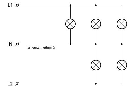
Good afternoon, please tell me how to be in this situation to the left, the output of the plate will need 380v which I want to transfer a wire through which I want to power a few more, as you can see, my standard wires where everything is clear, but in the old I don’t understand where. Thanks in advance
Good day to all. Just a few minutes ago I went up to the local electrician in the case, and he leads the phase with a yellow-green wire. I am indignant: "What are you doing." And in response: “And I do not have another wire.” And I have come across this many times. (It was like this: the phase is connected to the casing of the shield, and the neutral is connected to the line.)
Conclusion: do not trust the color coding of wires, be sure to check.
I also encountered this many times. And he himself had to lead the phase with a yellow-green wire because there was no other, though he wrapped it with white electrical tape.🙂
Hello. Tell me how to choose if the wires are white, blue, brown? thank
Whom to choose? Where to connect the phase and zero? Read the article, everything is described in it: zero is blue, phase is brown. Earth left over. Also, the author of the first comment wrote everything perfectly.
When checking for the presence of a phase, use the indicator lamps - this is an active load. All of these indicator probes, like testers sometimes show miracles - this is a passive load. If the wiring is in a loop, then there may be coils in the circuit, for example, starters that can work, like autotransformers and the tester will show you instead of 220v, already ... 800. I would like to ZhEK electricians who use indicators, without an active load - I beat my hands off. More than once encountered at work with such.
I advise the first - to find zero or earth, then draw this zero with a loop through all the rooms and “dance” from it. You hook the control to zero (a bulb in the socket and two wires), find the phase, then feed this phase into the box, through the same control to the next junction box, then connect it to the cable. On the other side, find the phase with such control, the phase will be supplied through the control lamp, and this is about half the phase voltage, and even if it “clicks” it will not kill (checked, but I do not advise checking). Because of laziness, I connect everything energized. In addition, when you connect a load, such as a chandelier, it will light up, after turning on the switch it is dim, but it will light up, which will correspond to the correct connection. When everything is connected, remove the control and twist the wires, everything will work in full phase. Do not count heavily on the earth in the switchboard, especially in high-rise buildings. There the “earth” was carried out as follows: the earth bus was welded, as it should be, where it was visible to the selection committee. Then the tire went into a mine, for example, an elevator, then left the mine chute, you can see the grounding bus (if the metalworkers have not yet stolen) near the garbage chute door, then this tire was simply buried in the ground when making steps before the entrance. It was supposed to make the ground loop, as expected: steel pins had to be driven into the ground, boiled together with fittings and to them, after that the ground bus. Nobody did this, because there was a race for the construction of housing. I worked as an electrician for repair and installation of elevators 36 and I know how the builders worked. It was such that when you connect the control to the phase, and then alternately to zero shield, which is on the ground of the house and on the cold water pipe, the control burned brighter on the water pipe than on that "ground".
PE wire means PROTECTIVE EARTH, which is translated from English as PROTECTIVE EARTH or whatever you like to translate while retaining the meaning and meaning. Accordingly, PEN means PROTECTIVE EARTH NEUTRAL, that is, a neutral connected to protective earth.
The wires on the lamp are white and yellow. What is what?
99.9999% probability that it makes no difference. Just these colors chosen. Is it a lamp for alternating current 220V or for direct current 12V?