What is a rotor and stator in an electric motor
What is a rotor?
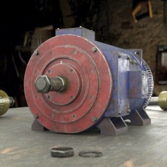
The rotor, also sometimes called an anchor, is a movable, that is, a rotating part in a generator or electric motors, which are universally used in household and industrial equipment.

If we consider the rotor of a DC motor or a universal commutator motor, then it consists of several main components, namely:
- Core. It is made of many stamped thin metal plates isolated from each other by a special dielectric or simply an oxide film, which conducts current much worse than pure metal. The core is drawn from them and is a “layer cake”. As a result, the electrons do not have time to accelerate due to the small thickness of the metal, and the heating of the rotor is much less, and the efficiency of the entire device is higher due to the reduction of losses. This design decision was made to reduce Foucault eddy currentsthat inevitably occur during engine operation due to magnetization reversal of the core. The same method of dealing with them is also used in AC transformers.
- Windings. Around the core in a special way is wound a copper wire coated with varnish insulation to prevent the appearance of short-circuited turns, which are unacceptable. The entire winding is additionally impregnated with epoxy resin or varnish to fix the windings so that they are not damaged by vibration from rotation.
- The rotor windings can be connected to the collector - a special unit with contacts, securely mounted on the shaft. These contacts are called lamellas; they are made of copper or its alloy for better transmission of electric current. Brushes, usually made of graphite, slide on it, and at the right moment electric current is supplied to the windings. This is called a sliding contact.
- The shaft itself is a metal rod, at its ends are seats for rolling bearings, it can have threads or recesses, keyways for attaching gears, pulleys or other parts driven by an electric motor.
- A fan impeller is also placed on the shaft so that the engine cools itself and does not have to install an additional device for heat dissipation.
It is worth noting that not every rotor has windings, which, in essence, are an electromagnet. Instead, permanent magnets can be used, as in brushless DC motors. But an asynchronous motor with a squirrel-cage rotor in its usual form does not have windings at all; instead, squirrel-cage metal rods are used, but more on that below.
What is a stator?
A stator is a fixed part in an electric motor. Usually it is combined with the body of the device and is a cylindrical part. It also consists of many plates to reduce heating due to Foucault currents, without fail varnished. At the ends are seats for sliding or rolling bearings.

The design is called a stator package; it is pressed into the cast-iron case of the device. Inside this cylinder, grooves are made for the windings, which, like the rotor, are impregnated with special compounds so that the heat is distributed more evenly across the device and the windings are not rubbed against each other by vibration.
Stator windings can be connected in different ways, depending on the purpose and type of electric machine. For three-phase motors, star and delta connection types are applicable. They are presented in the diagram:

To make connections, a special junction box (“boron”) is provided on the device case. The beginning and ends of three windings are brought into this box and special terminal blocks of various designs are provided, depending on the power and purpose of the machine.
There are serious differences in the operation of the motors with different connections of the windings. For example, when connected by a star, the engine will start smoothly, but it will not be possible to develop maximum power. When connected by a triangle, the electric motor will give out all the torque declared by the manufacturer, but the starting currents in this case reach high values. The power grid may simply not be designed for such loads. Using the device in this mode is fraught with heating of the wires, and in a weak place (these are the connection points and connectors), the wire may burn out and cause a fire. The main advantage of induction motors is the convenience in changing the direction of their rotation, you just need to swap the connection of any two windings.
Stator and rotor in induction motors
Three-phase asynchronous motors have their own characteristics, the rotor and stator in them differ from those used in other types of electric motors. For example, a rotor can have two designs: squirrel-cage and phase. Consider the structural features of each of them in more detail. However, for starters, let's briefly look at how an asynchronous motor works.
A rotating magnetic field is created in the stator. It induces an induced current on the rotor and thereby sets it in motion. Thus, the rotor always tries to “catch up” with the rotating magnetic field.
It is also necessary to mention such an important feature of an induction motor as sliding of the rotor. This phenomenon lies in the difference between the rotor speeds and the magnetic field created by the stator. This is explained precisely by the fact that the current is induced in the rotor only when it moves relative to the magnetic field. And if the rotational speeds were the same, then this movement would simply not have occurred. As a result, the rotor tries to “catch up” the magnetic field in rotation, and if this happens, the current in the windings ceases to be induced and the rotor slows down. At this moment, the force acting on him grows, he begins to accelerate again. And so the effect of stabilization of the rotation speed is obtained, for which these electric motors are in great demand.

Squirrel cage rotor
It is also a structure consisting of metal plates that perform the function of a core. However, instead of a copper winding, rods or rods are installed there that do not touch each other and are short-circuited by metal plates at the ends. In this case, the rods are not perpendicular to the plates, but are directed at an angle. This is done to reduce pulsations of the magnetic field and moment. Thus, short circuits are obtained, and the name comes from here.

Phase rotor
The main difference between a phase rotor and a short-circuited one is the presence of a three-phase winding, laid in the grooves of the core and connected in a special collector with three rings instead of lamellas. These windings are usually connected by a "star". Such electric motors are more labor-intensive in production due to the complexity of the design, however, their starting currents are lower than that of motors with a squirrel-cage rotor, and they are also more amenable to adjustment.

We hope that after reading this article you no longer have questions about what a rotor and stator of an electric motor are and what their principle of operation is. Finally, we recommend watching a video in which this issue is clearly considered:
Related materials: