What is a resistor and why is it needed in an electrical circuit
Definition
The resistor comes from the English “resistor” and from the Latin “resisto”, which in translation into Russian sounds like “resist”. In Russian-language literature, the word "resistance" is used along with the word "resistor". From the name, the main task of this element is clear - to resist electric current.
It belongs to the group of passive elements, because as a result of its operation, the current can only decrease, that is, unlike active elements, passive ones alone cannot amplify the signal. Which of the second Kirchhoff's Law and Ohm's Law means that when the current flows through the resistor, the voltage drops, the value of which is equal to the value of the flowing current, multiplied by the resistance value. Below you see how resistance is indicated on the diagram:
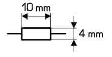
The symbol on the diagram is easy to remember - it is a rectangle, according to GOST 2.728-74, its dimensions are 4x10 mm. There are designations for resistors of different dissipation powers.
Views
The classification of resistors occurs according to a number of criteria. If we talk about discrete components, then according to the installation method they are divided into:
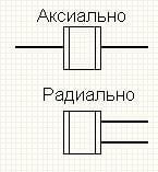
- Output. Used for mounting through a printed circuit board. Such elements have conclusions located radially or axially. In the people, conclusions are called legs. This type of resistor was actively used in all old devices (20 and more years ago) - old TVs, receivers, generally everywhere, and now it is used in simple devices, as well as where the use of SMD components is difficult or impossible for some reason.
- SMD These are elements that do not have legs. The findings for the connection are located on the surface of the housing, slightly protruding above it. They are mounted directly on the surface of the circuit board. The advantage of such resistors is the simplicity and low cost of assembly on automated lines, saving space on the printed circuit board.
The appearance of the elements of two types you see in the figure below:
We already know what this component looks like, now we should learn about the classification according to manufacturing technology. Output resistors are:
- Wirewound. As a resistive component, a wire wound on the core is used, bifilar winding is used to reduce spurious inductance. The wire is selected from metal with a low temperature coefficient of resistance and low resistivity.
- Metal film and composite.As you might guess, here, metal alloy films are used as a resistive element.
Since the resistor consists of a resistive material, the role of the latter can be a wire or film with a high resistivity. What it is? Materials such as:
- manganin;
- constantan;
- nichrome;
- nickel;
- metal dielectrics;
- metal oxides;
- carbon and others.
SMD or chip resistors are thin-film and thick-film, using as resistive material:
| Material | Features where used |
| Nickel Chrome (Nichrome, NiCr) | in thin film, which are resistant to high humidity (moisture-resistant) |
| Ditantalum nitride (Ta2N). | TCR is 25 ppm / 0С (-55 ... + 1250С); |
| Ruthenium Dioxide (RuO2) | in thick film |
| Lead Ruthenite (Pb2Ru2O6) | in thick film |
| Bismuth Ruthenite (Bi2Ru2O7) | in thick film |
| Vanadium Doped Ruthenium Dioxides (Ru0.8V0.2O2, Ru0.9V0.1O2, Ru0.67V0.33O2) | — |
| Lead oxide (PbO) | — |
| Bismuth iridium (Bi2Ir2O7) | — |
| Nickel alloy | In low-impedance (0.03 ... 10 Ohm) thin-film products |
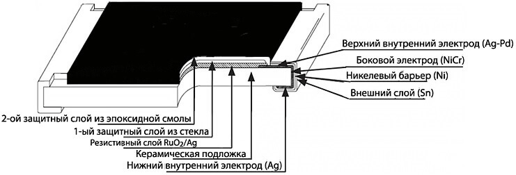
The figure below shows what the resistor consists of:
By design, they distinguish:
- Permanent. They have two conclusions, and you cannot change the resistance - it is constant.
- Variables These are potentiometers and tuning resistors, the principle of which is based on the movement of the sliding contact (slider) along the resistive layer.
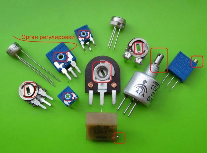
- Non-linear. The resistance of components of this type changes under the influence of temperature (thermistors), light radiation (photoresistors), voltage (varistors) and other quantities.
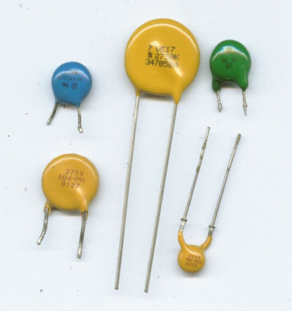
And also as intended - general and special. The latter are divided into:
- High resistance (the resistance range is tens of megohms - TO units, at operating voltages up to 400V)
- High-voltage (designed to operate in circuits with voltages up to tens of kV).
- High-frequency (a feature of working at high frequency is the requirement for low intrinsic inductances and capacitances. Such products can work in circuits with a signal frequency of hundreds of MHz).
- Precision and super-precision (these are products with a high accuracy class. They have a tolerance of deviation from the nominal resistance of 0.001 - 1%, while conventional tolerances can be 5% and 10% or more).
Principle of operation
The resistor is installed in an electrical circuit to limit the current flowing through the circuit. The magnitude of the voltage that drops on it is calculated simply - according to Ohm's law:
U = IR
The voltage drop is the number of Volts that appear on the terminals of the resistor when current flows through it. Accordingly, if the voltage drops across the resistor and current flows through it, it means a certain power is released into it. In physics, there is a well-known formula for finding power:
P = UI
Or to speed up the calculations, it is sometimes convenient to use the power formula through resistance:
P = u2/ R = I2R
How does a resistor work? Each conductor has a specific internal structure. When an electric current flows, electrons (charge carriers) collide with various inhomogeneities of the structure of matter and lose energy, it is released in the form of heat. If it’s hard for you to understand, then the principle of resistance in simple words can be said like this:
This is a value that shows how difficult it is for an electric current to flow through a substance. It depends on the substance itself - its resistivity.
Where: p is the resistivity, l is the length of the conductor, S is the cross-sectional area.
Main characteristics
To choose the right resistor, it is important to know what characteristics you need to look at when choosing. Its main parameters include:
- Rated resistance
- Maximum power dissipation.
- Tolerance or accuracy class. It depends on how much percent the resistance of parts from this class can differ from the declared one.
In most cases, this information is sufficient. Beginners often forget about the permissible power of the resistor, and they burn out.You can calculate how many watts are allocated to the resistor using the formula specified in the previous section of the article. Buy resistors with a power margin of 20-30%, more is better, less is not necessary!
Where and for what is applied
We already considered that the resistor is designed to limit the current in the circuit, now we will look at several practical examples where the resistor is used in electrical engineering.
The first area of application is current limitation, for example, for powering LEDs. The principle of operation and calculation of such a circuit is that the nominal operating voltage of the LED is subtracted from the voltage of the power source, the sum is divided by the rated (or desired) current through the LED. As a result, you get the rating of the limiting resistance.
Rogre= (Upower supply-Urequired) / Inominal
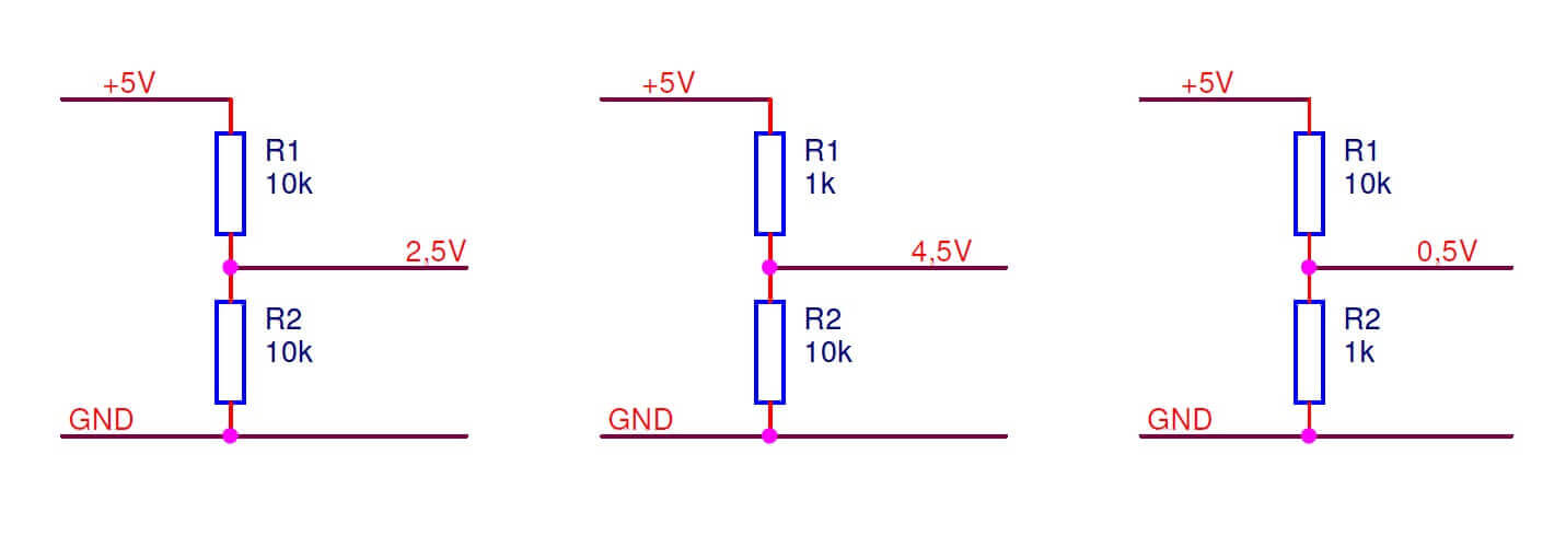
The second is the voltage divider. Here, the output voltage is calculated by the formula:
Uout= Uin(R2 / R1 + R2)
Also, the resistor has found application for setting the current for transistors. In essence, the same limiter circuit discussed above.
Finally, we recommend watching a useful video on the topic of the article:
We examined what are the resistors, their purpose and principle of operation. This is an important element from which to begin the study of electrical engineering. To calculate the circuits with him, they use Ohm's law and active power, and in high-frequency circuits, reactive parameters - stray capacitance and inductance - are also taken into account. We hope the information provided was useful and interesting for you!
Related materials:








Good day.
The formula in the voltage divider is incomprehensible, at least according to the first circuit, the 2.5 V output does not work in any way, judge for yourself
5 * (10 \ 10 + 10) = 5 * 11 = 55 in
what is the trick?
maybe it will be more correct to write like that
5(10\(10+10))=5(10\20)