What is transient contact resistance?
The causes of the phenomenon
Connecting contacts combine two or more conductors in an electrical circuit. A conductive contact is formed at the junction, as a result of which current flows from one area of the circuit to another.
If the contacts are laid on top of each other, a good connection will not be ensured. This is because the surface of the connecting elements is uneven and the touch is not carried out on their entire surface, but only at some points. Even if the surface is carefully sanded, minor hollows and tubercles will still remain on it.
Some books on electrical devices provide a photo where the contact area is visible under a microscope and it is much smaller than the total contact area.
Due to the fact that the contacts have a small area, this gives a significant transition resistance for the passage of electric current. Transient contact resistance is such a value that occurs at the moment the current passes from one surface to another.
In order to connect the contacts, various methods of pressing and fastening the conductors are used. Pressing is the effort by which surfaces interact with each other. Mounting methods are:
- Mechanical connection. Apply various bolts and terminal blocks.
- Contact occurs due to the elastic pressure of the springs.
- Soldering, welding and crimping.
What does resistance depend on?
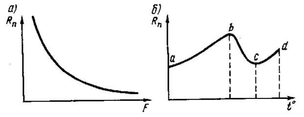
When two conductors come into contact, the total area and number of sites depends on both the level of pressing force and the strength of the material itself. That is, the transition contact resistance depends on the pressure: the more the force, the less it will be. Only the pressure should be increased to a certain figure, since at high mechanical loads the transition resistance practically does not change. Yes, and such strong pressure can lead to deformation, as a result of which the contacts can break.
Also, the transition resistance of the contacts depends significantly on temperature. When the electric voltage passes through the conductors and their surfaces, the contacts heat up and the temperature rises, as a result, the transition resistance increases. Only this increase is slower than the increase in the resistivity of the material of the structure, since, when heated, the material loses its hardness.
The stronger the device heats up, the more intensive the oxidation process, which in turn also affects the increase in transition resistance. So, for example, a copper wire is actively oxidized at a temperature of 70 ° C. At ordinary room temperature (about 20 ° C), copper is slightly oxidized and the forming oxidizing film is easily destroyed by compression.
The picture shows the dependence of the value on pressing (A) and temperature (B):
Aluminum oxidizes at room temperature much faster and the oxidizing film that forms is more stable and has a high reaction. Based on this, we can conclude that it is difficult to achieve normal contact with stable values during the use of the device. Therefore, the use of aluminum conductors in electrics is dangerous.
In order to obtain stable and durable connecting contacts, it is necessary to clean and process the cable surface itself qualitatively. Also create enough pressure. If everything is done correctly (regardless of which method the connection was made), then the meter will indicate a stable value.
Measurement technique
Measuring the transition resistance is necessary at the specified values of current and voltage. How to determine this value? Conventional devices in the form of an ohmmeter or tester will not work, as they pass currents of 0.5–1 mA through an electric circuit at voltages up to 2 V. With such small loads, most powerful devices cannot provide the passport data of this phenomenon. Its definition is possible if you assemble a conventional measurement scheme. It is provided below:
Ballast resistance (R) suspends the current through the contacts, and a decrease in voltage on them at a certain current makes it possible to determine the transition resistance by the formula. When selecting elements in the circuit, it is necessary to enter during testing the currents provided by the table below (data are indicated taking into account the norms, PUE and GOST):
| Operating current of relay contacts, A | Contact resistance test current, mA |
| 0,01 – 0,1 | 10 |
| 0,1 – 1 | 100 |
| >1 | 1000 |
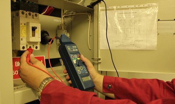
Instead of the measurement scheme provided above, you can use special instruments, for example, the Microohmmeter F4104-M1 or an imported analogue of C.A.10. How to measure this value is shown in the video:
It is important to note that the test results depend on how dirty the contacts are and what temperature they have. Therefore, when making measurements, it is necessary to choose a current and voltage that will correspond to certain conditions for using the relay in the indicated circuit.
What should be the transient contact resistance? The maximum allowable value of this value is standardized and equals 0.05 ohms.
When establishing large loads, do not forget about the initial high contact resistance. After switching, it significantly decreases under the influence of electrical cleaning. If the device is used in signal circuits, then this value can be neglected.
That's all I wanted to tell you about what the contact resistance of the contacts is, what is its acceptable value and how are the measurements of the value. We hope the information was useful and interesting for you!
It will be useful to know:





Thank you for the video, because the laboratory arriving to measure the contact resistance of the contacts measures the ground wire from one outlet to another, and if I understand correctly, they simply measure the resistance of the conductors plus the resistance of the contacts in the boxes.
PTEEP obliges to make measurements: 1.Measurement of transition resistance of grounding connections with grounding elements (Appendix 3, p. 26.1). 2. Transient contact resistance between the grounded installation and its element (Appendix 3, p. 28.6). In both cases, the resistance should be no more than 0.05 ohms. How, in practice, measurements can be taken. Thanks in advance