What is isolated neutral and where is it used?
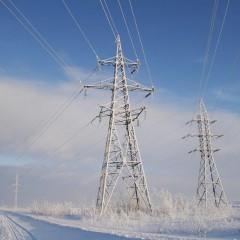
Currently, an isolated neutral is difficult to find in everyday life, you will never encounter it if you make wiring in apartments. While high-voltage lines it is actively used, as well as in some cases in 380V networks. We will tell you more about what an isolated neutral network is and what features it has in simple words in this article.
What it is
The definition of “isolated neutral” is given in chapter 1.7. PUE, in paragraph 1.7.6. and GOST R 12.1.009-2009. Where it is said that isolated is the neutral at the transformer or generator, not connected to the grounding device at all, or when it is connected through protection, measurement, and signaling devices.

Neutral is the point at which the windings of transformers or generators are connected when turned on according to the "star" scheme.
Among electricians, there is a misconception that the abbreviated name of isolated neutral is IT system, according to the classification of clause 1.7.3. Which is not entirely true. The same paragraph says that the designations TN-C / C-S / S, TT and IT are accepted for networks and electrical installations with voltage up to 1 kV.
In the same chapter 1.7 of the EIC there is clause 1.7.2. where it is said that with regard to electrical safety measures, electrical installations are divided into 4 types - insulated or deafly grounded up to 1 kV and above 1 kV.
Thus, there are some differences in the safety and application of such a network in different voltage classes and it is at least incorrect to call a 10 kV line with an isolated neutral "IT system". Although schematically - almost the same.
In networks up to 1 kV
General information
Let's see where, how and in what cases they use an isolated neutral in electrical installations with voltage up to 1000 V, the so-called IT system. In the PUE chapter 1.7. Section 1.7.3. a definition similar to that given above is given, but it is slightly different. It says that enclosures and other conductive parts in IT systems must be grounded. Consider how it looks in the diagram.

Since the neutral of the IT network transformer is not connected to earth, in simple terms, we do not have a dangerous potential difference between the ground and phase wires. And accidentally touching 1 live wire in the IT system is safe. Due to the relatively low voltage, capacitive phase conductivity is neglected here.
In networks with isolated neutral, there is no pronounced phase and zero - both conductors are equal.
The current through the human body is equal to:
Ih = 3Uf/ (3rh+ z)
Uf - phase voltage; rh - resistance of the human body (1 kOhm is accepted); z is the total insulation resistance of the phase relative to the ground (100 kOhm or more per phase).
The current in this case returns to the power source through the insulation of the wires, and not to the ground, as is the case with TN.
Since the insulation resistance is more than 100 kOhm per phase, the current through the body will be units of milliamps, which will not cause harm.
Another feature of this system is that leakage currents to the casing and short-circuit currents to the ground will be low. As a result, protective automation (relay or circuit breakers) do not work in the way that we are used to in networks with a grounded neutral. But the insulation resistance monitoring system works.
Accordingly, with a single-phase circuit of a three-phase line, the system will continue to function. In this case, the voltage on the two remaining wires increases relative to the ground. If a person touches a phase wire, he falls under line voltage.

In connection with this design, there are no two types of voltage in a network with an isolated neutral, in contrast to a light-earthed one, where between the phases Ulinear (in everyday life 380V), and between phase and zero Uphase (220V). To connect a single-phase load to the network with an IT system with a voltage of 380V, you can use step-down transformers of type 380/220 and connect the devices between the two phases to a linear voltage.
Scope of application
Let's talk about where such a solution is used. This power supply system was used in domestic power grids to transfer electricity to residential buildings during the Soviet era. Especially for the electrification of wooden houses, where when using a grounded neutral, the risk of a fire due to earth faults increased.
From the point of view of electrical safety, the difference between an isolated and a grounded neutral in the power supply of houses is that if one of the conductors touches the grounded conductive parts in the IT network, for example wall fittings or water pipes, the network will continue to function due to low leakage currents.
Accordingly, neither the residents, nor anyone else will know about the problem until, while someone touches one of the wires and the pipeline, someone will be shocked.

In a system with a grounded neutral, at least differential protection will operate, and with a "good" metal circuit, the circuit breaker will open. With the beginning of the massive construction of panel houses (the so-called Khrushchev), they abandoned it and in the 60-80s switched to TN-C, and in the late 90s on TN-C-S, about the reasons read below.
Currently, isolated neutral is used wherever it is necessary to provide increased security or whether it is not possible to make grounding, namely:
- In the sea - on ships, oil and gas platforms, where the use of the platform body as grounding is impossible due to the anode protection, and in places where current flows into the water, it will begin to rust and rot intensely.
- In mines and other mining sites (with a voltage of 380-660V).
- In the underground.
- On lighting and control circuits in stationary cranes, etc.
- Also in domestic gasoline, gas or diesel generators at the output terminals is an isolated neutral.
It can be found not only in the form that we presented in the diagram above, but also in the form of step-down and isolation transformers that are used to power portable lighting devices (not more than 50V or 12V PTEEP p. 2.12.6.) And other equipment or tools, including those with which they work in closed and damp rooms.
To summarize
We figured out why we need an isolated neutral up to 1 kV, now we will list the advantages and disadvantages of the power supply system with an isolated neutral for dummies in electrics.
Benefits of use:
- Great security.
- Greater reliability, which allows you to use, for example, for lighting in hospitals.
- The economic factor - in a three-phase network with isolated neutral, it is possible to transfer electricity through the smallest possible number of wires - in three.
- The system will continue to operate with single-phase earth faults.
Disadvantages:
- Earth faults increase the risk of use, as the power supply continues.
- Small short-circuit currents.
- No sparks during primary fault.
In networks above 1000 V
Currently, isolated neutral is most often used in networks with a medium voltage class (1-35 kV). For a network of 110 kV and higher - solid earthed. Due to the fact that during short-circuit to ground, the voltage, as was said, rises to linear, so in the 110 kV transmission line, the phase voltage (between the ground and the phase conductor) is 63.5 kV. With short-circuit to the ground, this is especially important, and allows to reduce the cost of insulating materials.

By the way, in KTP with a higher voltage of up to 35 kV, the primary windings of the transformers are connected into a triangle, where there is no neutral as such.

Low short-circuit currents and the ability to work with single-phase short-circuit on overhead lines - in distribution networks are especially important and allow you to organize uninterrupted power supply. In this case, the angle of shift between the phases remaining in the work remains unchanged - at 120 °.
At voltages of thousands of volts, the capacitive conductivity of the phases cannot be neglected. Therefore, touching the VLEP wires is dangerous to human life. In normal mode, the currents in the phases of the source are determined by the sum of the loads and capacitive currents relative to the ground, while the sum of the capacitive currents is zero and the current in the ground does not pass.
If we omit some details in order to set out in a language understandable for beginners, then with a short to ground, the voltage relative to the ground of the damaged phase approaches zero. Since the voltages of the other two phases increase to linear values, their capacitive currents increase by √3 (1.73) times. As a result, the capacitive current of a single-phase short circuit is 3 times higher than normal. For example, for a 10 kV high-voltage transmission line 10 km long, the capacitive current is approximately 0.3 A. When a phase is shorted to ground through an arc, hazardous overvoltages up to 2-4U occur as a result of various phenomena.f, which leads to a breakdown of insulation and interphase short circuit.

To exclude the possibility of occurrence arc and eliminate possible consequences, the neutral is connected to the earth through an arc suppression reactor. At the same time, its inductance is selected according to the capacitance in the place of a short circuit to ground, and also so that it ensures the operation of relay protection.

Thus, thanks to the reactor:
- I decreases muchshort
- The arc becomes unstable and quickly goes out.
- The increase in voltage after the extinction of the arc is slowed down, as a result, the likelihood of the re-occurrence of the arc and switching current is reduced.
- The currents of the reverse sequence are small, therefore, their effect on the rotating rotor of the generator does not have a significant effect.
We list the pros and cons of high-voltage networks with isolated neutral.
Benefits:
- For some time it can work in emergency mode (with short circuit to ground)
- An insignificant current appears in the places of malfunction, provided that the current capacity is small.

Disadvantages:
- Complicated fault detection.
- The need to isolate line voltage installations.
- If the circuit lasts a long time, then a person may be shocked by electric shock if it falls under step voltage.
- With 1-phase short circuit, normal operation is not ensured relay protection. The value of the fault current directly depends on the branching circuit.
- Due to the accumulation of insulation defects from exposure to arc overvoltages, its service life is reduced.
- Damage can occur in several places due to breakdown of insulation, both in cables, and in electric motors and other parts of the electrical installation.
This concludes the review of the principle of operation and features of networks with isolated neutral. If you want to supplement the article or share your experience - write in the comments, we will publish it!
Related materials: