What is a phase indicator and how to use it?
Need for application
There are situations during which a three-phase type network connection must be made in phase sequence. The fact is that the direction in which the rotor rotates during connection to an asynchronous motor network is not a guarantee to indicate exactly if we are not strictly following the phasing procedure.
For example, when it comes to operating a fan for an appropriate system or drive for pump operation, it is necessary to clearly know the direction of rotation. This ensures the execution of the technological cycle. Therefore, it is important to comply with the connections in series. In order to solve this problem, one should resort to the help of a special device called a phase indicator. This allows you to understand why it is needed. The scope of the phase indicator is quite wide and is constantly growing.

If the phasing is set correctly, then the phase sequence proceeds from A further to B and ends with C. The direction of rotation of the engine is also determined by the same order. For example, if the wires that feed the windings are connected in the correct order, then the motor rotor is operated conditionally clockwise. However, in a situation where two of these phases are changed, there will be a violation of the direction of rotation of the rotor. Then the technological process in which the engine is involved will simply be disrupted. This will lead to the fact that the equipment used in the drive will be broken and malfunction. After that, if you perform the reverse procedure with the phases, then the engine order will go back to normal and the process will be correct.
User manual
Phase indicators, as you know, are of several types. The simplest version of this device, which is typical for most situations, is a device of the I517M brand. It is essentially a small three-phase induction motor. It is very sensitive in terms of phase rotation. You can easily understand how the I517M phase indicator works and how it works, looking into its design.

The instructions for using the appliance are simple. As terminals for such a phase indicator, conclusions from the windings of a conventional stator are used. Proceeding from this, the rotation of the indicator-type disk, where an additional mark is applied, can indicate what the order of phase rotation is.This will be clear from the direction in which the phase indicator disk rotates. In a situation where all phases are connected in the correct way, the disk will rotate in the direction of the arrow on the watch. Otherwise, its direction of rotation will be reversed.
The layout on the disc is in contrast. This makes it possible without much difficulty to independently determine the direction in which it will rotate. Accordingly, if there is no connection to at least one phase, the disk will not rotate.
How to use an old-style phase indicator is shown in the video (using the example of the FU-2 device):
In addition to the phase indicator presented, there is another device that is quite simple in its design. It is based on incandescent lamps. Neon lamps, or the most ordinary LEDs, can also be used in the design of the device. The main factor determining the effectiveness of such a phase indicator is the resistance of complex type circuits. This feature is explained by the type of connection of the bulbs. They are connected directly through capacitors and act as signaling devices.

In a situation where, for example, the first of the bulbs is fed through a capacitor, its brighter glow occurs. The subsequent light bulb will carry out its power through a resistor. Therefore, the intensity of its glow will be noticeably less. Also, it may not glow at all. It follows that it is possible to determine the order with which the phases on the engine will alternate. You only need to understand in which branch the resistor is located, and where the capacitor is on.
The described principle of operation is fundamental in the design of phase-indicating circuits that operate on neon-type lamps or on LEDs. The purpose of such lamps is clear. There are devices of a more complex design. They are created on the electronic principle of operation. In this case, phase-type stress analysis is performed using a graphical technique.
It is necessary to consider the simplest example of such a phase indicator. This is a simple device, which anyone can assemble if desired. The structure contains three branches of non-symmetric type. Each of these branches has its own installed components. Oddly enough, a simple phase-indicator circuit creates good conditions in order to determine the order with which phases in a three-phase type network will alternate. In this case, it is not necessary to conduct an additional connection to the zero-type wire.

This is a very simple principle, which consists in the appearance of phase currents of an asymmetric type, when there is an asymmetric load. Therefore, the voltage drops on the components of the reactive and active type circuits will also be completely different.
In one of the phases there is a capacitive load. The remaining phases have an active load. During the pairing of such a circuit to a three-phase type network, if the condition for the proximity of the ratings to it is satisfied, the phase voltages will have the following indicators: branch B will give data 1.49 * Uf, designation branch C - 0.4 * Uf. In this case, Uf is the phase voltage of the usual type for a symmetric three-phase network (for example, 220 V).
It follows that in a situation where the connection is made in the correct way, as well as all the phases are in the order of A, B and C, the branch labeled B will have a voltage that is three times higher than that of C. Moreover, the voltage at the resistor is 60 volts. Then a neon bulb will probably emit light during operation. This will be a light indication of the correct phasing.
In the future, if at least a couple of phases are reversed, a voltage drop across the resistor will occur. However, this fall will not be enough to power a neon bulb. Then it will not emit light. This is direct evidence that phasing is incorrect.Thus, the reverse procedure will be carried out in the engine, providing for a change in the direction of rotation of its shaft.
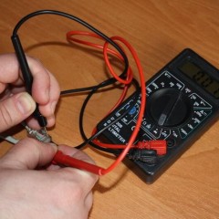
Typically, the device includes a housing and three probes. Each of them has its own color marking. In some situations, an additional letter designation is used. Usually used green, red and yellow colors. The same sequence can be - red, yellow and green.
Next, the probes are installed on phase-type conductors and we press a button. There are devices where such a button is present. However, some devices do not have it. Then they simply install the probes, and the device produces a light alarm. Additionally, there may be an audio alarm. The sound is intermittent when the phasing is correct and continuous in a different situation.
The video below clearly shows how to use the phase indicator:
Important to rememberthat the mains voltage is dangerous to humans. Therefore, care must be taken when using the phase indicator!
That's all we wanted to tell you about what a phase indicator is, how it works and what it is used for. We hope that the provided instruction was useful and interesting for you!
Surely you do not know:


And how to check with this device whether the phase rotation is the same at the outputs of three-phase transformers to include them in parallel operation? the readings of the device (which you for some reason call the phase indicator) do not really give an answer where is which phase. In this case, there is ambiguity, (the rotating field will be correct for different alternations), but the situation may turn out: 1 - ABC transformer, 2 - VSA transformer, the rotating magnetic field will be the same for this device, but when you turn on the transformers in parallel operation, a lot of women ! 😊. Alas, this is not a phase indicator