What is a voltage divider and what is it used for
Definition
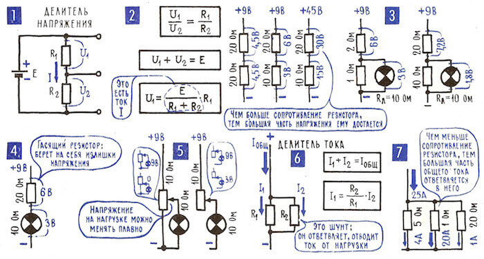
A voltage divider is a device or device that lowers the level of the output voltage relative to the input, in proportion to the transmission coefficient (it will always be below zero). He got this name because it represents two or more series-connected sections of the chain.
They are linear and non-linear. In this case, the former are active or reactive resistance, in which the transmission coefficient is determined by the ratio of Ohm's Law. To pronounced nonlinear dividers include parametric voltage stabilizers. Let's see how this device is arranged and why it is needed.
Types and principle of action
It is immediately worth noting that the principle of operation of the voltage divider is generally the same, but depends on the elements of which it consists. There are three main types of linear circuits:
- resistive;
- capacitive;
- inductive.
The most common divider on resistors, because of its simplicity and ease of calculation. On his example, and consider the basic information about this device.
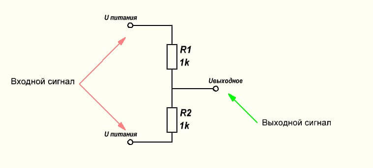
Any voltage divider has Uinput and Uoutput if it consists of two resistorsif there are three resistors, then there will be two output voltages, and so on. You can make any number of stages of division.
Uinput is equal to the supply voltage, Uoutput depends on the ratio of resistors in the arms of the divider. If we consider a circuit with two resistors, then the top, or as it is also called, the damping arm will be R1. The lower or exit arm will be R2.
Suppose we have a power supply of 10V, the resistance R1 is 85 Ohms, and the resistance R2 is 15 Ohms. Need to calculate Uoutput.
Then:
U = I * R
Since they are connected in series, then:
U1 = I * R1
U2 = I * R2
Then if you add the expressions:
U1 + U2 = I (R1 + R2)
If we express the current from here, we get:
Substituting the previous expression, we have the following formula:
Let's calculate for our example:
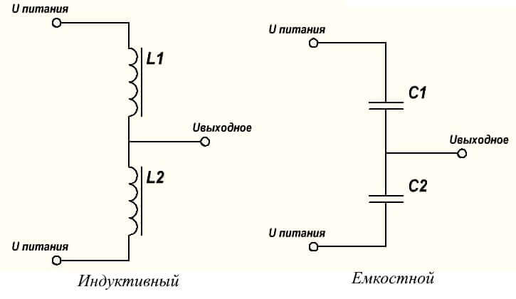
The voltage divider can be performed on reactances:
- on the capacitors (capacitive);
- on inductors (inductive).
Then the calculations will be similar, but the resistance is calculated using the formulas below.
For capacitors:
For inductance:
The peculiarity and difference of these types of dividers is that the resistive divider can be used in AC and DC circuits, and capacitive and inductive only in AC circuits, because only then will their reactance.
Interesting! AT In some cases, a capacitive divider will work in DC circuits, a good example is the use of such a solution in the input circuit of computer power supplies.
The use of reactance is due to the fact that during their operation, not so much heat is released as when using active resistances (resistors) in structures
Examples of use in the circuit
There are many schemes where voltage dividers are used. Therefore, we will give several examples at once.
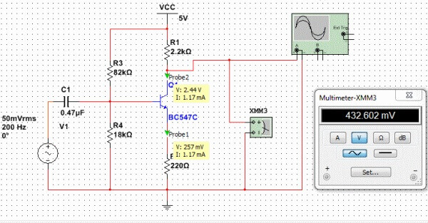
Suppose we design an amplifier stage on a transistor that operates in class A. Based on its principle of operation, we need to set the bias voltage (U1) on the basis of the transistor so that its operating point is on the linear segment of the I – V characteristic, so that the current through the transistor was not excessive. Suppose we need to provide a base current of 0.1 mA at U1 of 0.6 Volts.
Then we need to calculate the resistance in the arms of the divider, and this is the inverse calculation relative to what we have given above. First of all, they find the current through the divider. So that the load current does not greatly affect the voltage on its shoulders, we set the current through the divider an order of magnitude higher than the load current in our case 1 mA. Power supply let it be 12 volts.
Then the total resistance of the divider is:
Rd = U supply / I = 12 / 0.001 = 12000 Ohm
R2 / R = U2 / U
Or:
R2 / (R1 + R2) = U2 / U power
10/20=3/6
20*3/6=60/6/10
R2 = (R1 + R2) * U1 / U power = 12000 * 0.6 / 12 = 600
R1 = 12000-600 = 11400
Check the calculations:
U2 = U * R2 / (R1 + R2) = 12 * 600/12000 = 7200/12000 = 0.6 Volts.
The corresponding upper shoulder will extinguish
U2 = U * R2 / (R1 + R2) = 12 * 11400/12000 = 136800/12000 = 11.4 Volts.
But this is not the whole calculation. For a complete calculation of the divider, it is necessary to determine the power of the resistors so that they do not burn out. At a current of 1 mA, power will be allocated to R1:
P1 = 11.4 * 0.001 = 0.0114 watts
And on R2:
P2 = 0.6 * 0.001 = 0.000006 watts
Here it is negligible, but imagine what kind of power would need resistors if the divider current was 100 mA or 1 A?
For the first case:
P1 = 11.4 * 0.1 = 1.14 watts
P2 = 0.6 * 0.1 = 0.06 watts
For the second case:
P1 = 11.4 * 1 = 11.4 watts
P2 = 0.6 * 1 = 0.6 watts
That is already considerable figures for electronics, including for use in amplifiers. This is not effective, therefore, pulsed circuits are currently used, although linear circuits continue to be used either in amateur constructions or in specific equipment with special requirements.
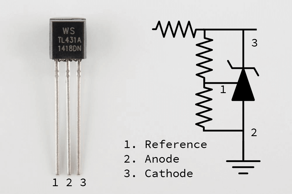
The second example is a divider for forming the U-reference for the adjustable zener diode TL431. They are used in most inexpensive power supplies and chargers for mobile phones. The connection diagram and calculation formulas you see below. With the help of two resistors, a point with a U-reference of 2.5 volts is created here.
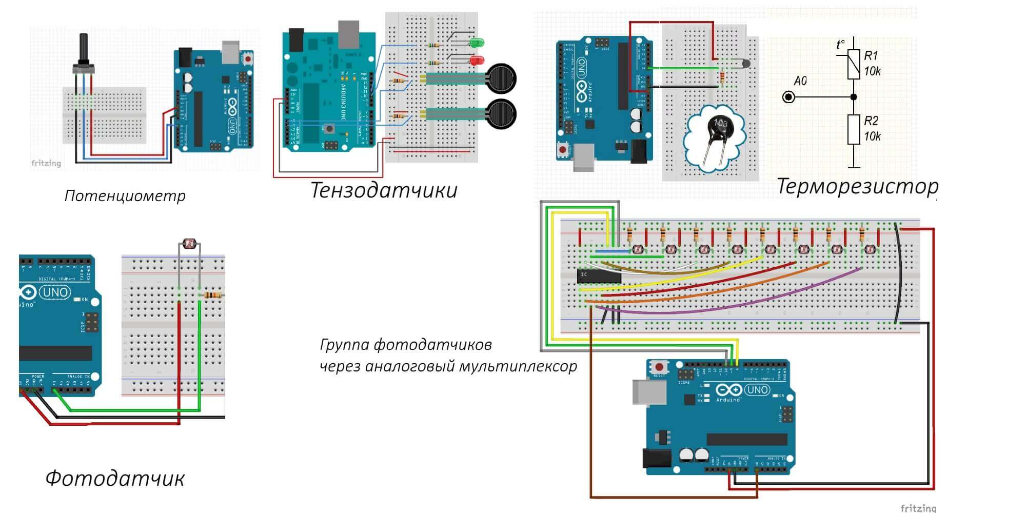
Another example is the connection of all kinds of sensors to microcontrollers. Consider several schemes for connecting sensors to the analog input of the popular AVR microcontroller, using the Arduino family of boards as an example.
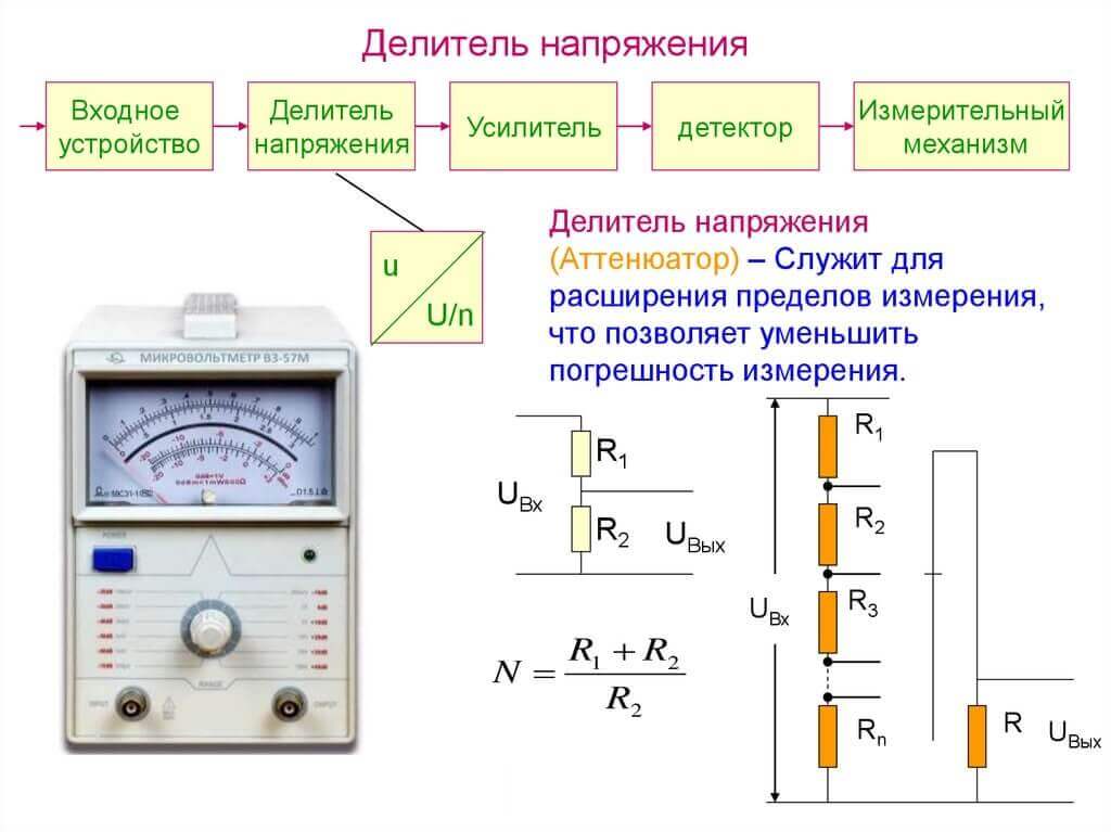
Measuring instruments have different measurement limits. Such a function is also realized using a group of resistors.
But this does not end the scope of voltage dividers. It is in this way that extra volts are extinguished while limiting the current through the LED, the voltage of the bulbs in the garland is also distributed, and you can also power a low-power load.
Nonlinear dividers
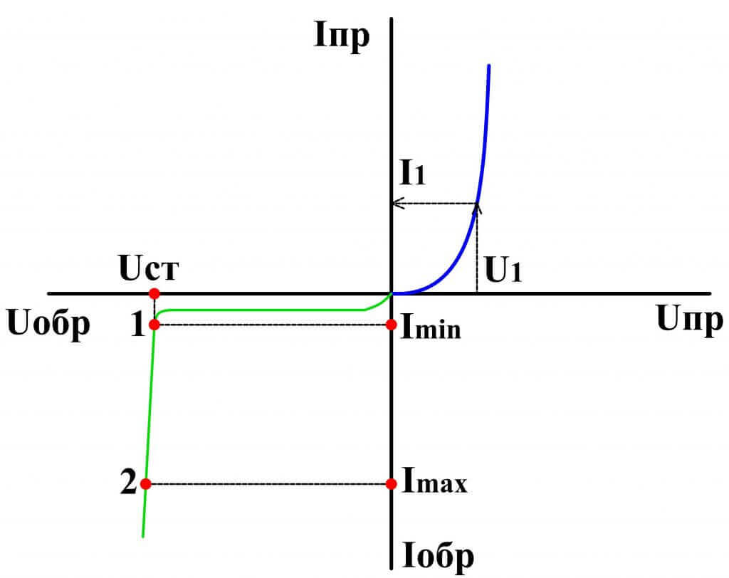
We mentioned that non-linear dividers include a parametric stabilizer. In its simplest form, it consists of a resistor and a zener diode. A zener diode in the circuit is similar to a conventional semiconductor diode. The only difference is the presence of an additional feature on the cathode.
The calculation is based on the stabilization of the Zener diode. Then if we have a zener diode of 3.3 volts, and the power supply is 10 volts, then the stabilization current is taken from the datasheet to the zener diode. For example, let it be equal to 20 mA (0.02 A), and the load current 10 mA (0.01 A).
Then:
R = 12-3.3 / 0.02 + 0.01 = 8.7 / 0.03 = 290 Ohms
Let's see how such a stabilizer works. The zener diode is included in the circuit in the reverse connection, that is, if Uoutput is lower than Ustabilization, the current does not flow through it. When U supply rises to U stabilization, an avalanche or tunnel breakdown of the PN junction occurs and a current, called the stabilization current, flows through it. It is limited by the resistor R1, on which the difference between the U input and U stabilization is suppressed. If the maximum stabilization current is exceeded, thermal breakdown occurs and the zener diode burns out.
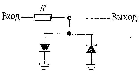
By the way, sometimes you can implement a stabilizer on diodes. The stabilization voltage then will be equal to the direct drop of the diodes or the sum of the drops in the diode circuit. You set the current suitable for the nominal value of the diodes and for the needs of your circuit. Nevertheless, such a solution is used extremely rarely. But such a device on diodes is better called a limiter, not a stabilizer. And a variant of the same circuit for AC circuits. So you limit the amplitude of the variable signal at the level of direct drop - 0.7V.
So we figured out what this voltage divider is and why it is needed. Examples where any of the variants of the considered circuits are used can be given even more, even the potentiometer is essentially a divider with infinitely adjustable transmission coefficient, and is often used in conjunction with a constant resistor. In any case, the principle of action, selection and calculation of elements remains unchanged.
In the end, we recommend watching a video on which we examine in more detail how this element works and what it consists of:
Related materials:

