What is a Hall sensor and where is it used?
Principle of operation and types
The use of sensors in various devices (in the tablet, in particular) is explained by their ability to respond to field changes and turn off when the magnetic cover of the case is closed. Due to this property, they are installed in washing machines, allowing you to control the speed of rotation of the drum. In simple terms - here the Hall sensor is used as a tachometer.

History reference
To understand the principle of operation of this element, you will need a small excursion into history. In 1879, the American physicist Hall discovered an interesting phenomenon related to the behavior of a conductor with current in a magnetic field. The test showed that if a current is passed through a copper plate placed between the magnets, a potential difference appears on its lateral faces. A logical question arises: how to check this voltage at home?

It turned out that in practice it can be measure with a multimeter or any other device that has the appropriate limits. The same can be done with any suitable tester or similar instrument.
The connection of the meter confirms that the moving electrons are deflected to the side under the influence of the magnetic field (perpendicular to the direction of their movement).
Important! The magnitude of this deviation or potential difference is proportional to the "power" of the magnets and the current through the plate.
On this basis, Hall concluded that such a conductor is a good tool for measuring the magnetic field. The operation of a special sensitive element called the Hall sensor is based on this effect. Having figured out how it works in each particular device, you can be sure of the final assimilation of its operating principle.
Classification
It is important to understand what Hall sensors are, and by what principle they are usually classified. According to the features of the work and why it is needed or for its intended purpose, the Hall sensor can have various designs. One of the varieties is analog devices that produce a continuous signal at the output.
In contrast, a digital element has only two discrete states (“zero” and “unit”). This type of device can be unipolar or have a bipolar type.The first of them works when a field of any polarity is detected and turns off when it disappears. That is, a unipolar digital sensor responds only to the absence or presence of magnetic tension. The considered features of each of the subspecies also help to understand what it is - a Hall sensor.
Unipolar sensors switch to the “unit” only when the field reaches the threshold level and are not able to determine its presence at weak tensions. The indicated property is a significant minus of such devices, significantly limiting the scope of their application. The bipolar sensor is triggered taking into account the polarity of the magnetic field, one of which turns it on, and the other turns it off.
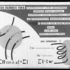
The conventional graphic designation of devices of this class is shown in the photo below:

Device and usage examples
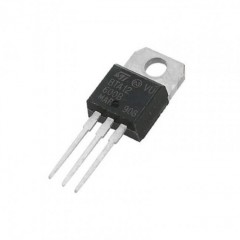
The simplest system with a Hall sensor includes the following elements:
- Permanent magnet (its function is to create a magnetic field).
- Movable rotor with blades or teeth.
- A special rod made of magnetic material (magnetic core).
- Plastic case.
In addition, the technical characteristic of the sensor provides for the use of microcircuits involved in the measurement process.
It is possible to understand the principle of operation of this device if you familiarize yourself with the detailed diagram of the inclusion of the Hall sensor in the measurement zone. The connection diagram and the essence of the sensor can be represented as follows:
- In the gap formed by the halves of the magnetic circuit, the metal rotor blades move.
- During their rotation, periodic shunting of the magnetic flux occurs.
- The integrated microcircuit provides for the determination of a zero induction index (at these moments the voltage at its output is maximum).
- The frequency of such bursts, calculated by the same chip, is used to judge the rotation speed of a controlled object (a motor shaft in a motorcycle, for example).
In order for this process to proceed normally, when the sensor is included in the measuring circuit, the pinout of this sample must be taken into account (it can be different).

Summarizing the considered scheme, it should be assumed that sensors of this class are capable of measuring the speed of rotation of the crankshaft of any moving vehicle. The universality of the sensor, which does not exclude the possibility of installing it in a scooter, for example, allows you to use the Hall sensor not only in complex technical devices, but also in ordinary household appliances.
Application in the ignition system and washing machines
When using the Hall sensor in the vehicle’s ignition system, it can be used to fix the moment of opening the distributor. In this case, it works as an analog converter, which determines the moments of interruption of the onboard power supply. Its use in the operating modules of the washing machine is based on the same principle, which allows determining the increase in the weight of the laundry by the speed of rotation of the drum.

Hall sensors are installed in some samples of measuring equipment. Most often they are equipped with contactless clamps used to measure current in conductors. The built-in device responds to changes in the electromagnetic field generated around the power cable. In addition, it is suitable for the gas handle of an electric bike, allowing you to control the angle of rotation.
In domestic conditions
In computer keyboards, these devices provide a non-contact way of taking information. The sensor, which is part of the household PC cooler, is able to control the polarity of the rotor windings, that is, change the direction of its rotation.


When using such an element in a smartphone, in particular, it provides turning off the device when placing it in a case with a “magnetic” fastener.

Considering the application of Hall sensors in simple words, we can say that its use in the technical field is practically unlimited.In the electronic constructor of Arduino, for example, there is a kit with such a sensor, which allows in practice to illustrate the Hall effect.

This is not the only example of its use for training purposes, helping novice users understand how to connect and use field structure sensors.
In conclusion, we note that the disadvantages of Hall sensors include their sensitivity to electromagnetic interference, which often occurs in operating circuits. In addition, the use of complex electronic modules in the design of the device to some extent affects its reliability, slightly reducing it. These disadvantages of the sensor are not considered as its defects, but simply taken into account when working with the equipment.
Now you know what a Hall sensor is, how it works and why you need it. We hope the information provided was useful and interesting!
Related materials: