3 DIY Timer Relay Assembly Ideas
Simplest option
An example of a constructor for a self-made assembly of a trip delay timer:
If desired, it is possible to independently assemble a time relay according to the following scheme:

The timing element is capacitor C1, in the standard kit of the kit, it has the following characteristics: 1000 μF / 16 V, the delay time in this case is approximately 10 minutes. Time adjustment by variable resistor R1. Board power 12 volts. The load is controlled through the relay contacts. You can not make the board, but assemble it on a breadboard or by mounting it on the surface.

In order to make a time relay, we need the following details:

A properly assembled device does not need to be configured and is ready to work. This home-made time delay relay was described in the journal "Radio" 2005.07.
Homemade timer-based NE 555
Another do-it-yourself electronic timer circuit is also lightweight and repeatable. The heart of this circuit is the NE 555 integrated timer chip. This device is designed to both turn off and turn on devices, the device diagram is presented below:

NE555 is a specialized chip used in the construction of various electronic devices, timers, signal generators, etc. It is quite common, so it can be found in any radio store. This microcircuit controls the load through an electromechanical relay, which can be used to turn on and off the payload.
The timer is controlled by two buttons: “start” and “stop”. To start the countdown, you must click on the "start" button. Disabling and returning the device to its original state is carried out by the stop button. The node that sets the time interval is a chain of variable resistor R1 and electrolytic capacitor C1. On their value depends on the delay time time relay.

With the given values of the elements R1 and C1, the time range can be from 2 seconds to 3 minutes. As an indicator of the state of operability of the structure, an LED connected in parallel with the relay coil is used. As in the previous circuit, its operation requires an additional external power supply of 12 volts.
In order for the relay to turn on itself immediately when it is supplied to the power board, you need to slightly change the circuit: pin 4 of the microcircuit is connected to the positive wire, pin 7 is disconnected, and pin 2 and 6 are connected together. You can learn more about this scheme from the video, which describes in detail the process of assembly and work with the device:
Relay on a single transistor
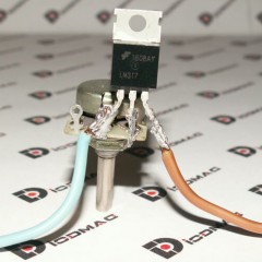
The easiest option is to use the time relay circuit on just one transistor, CT 973 A, its imported analogue BD 876. This solution is also based on the charge of the capacitor to the supply voltage, through a potentiometer (variable resistor). The highlight of the circuit is the forced switching and discharge of the capacitance through the resistor R2 and the return to its original starting position with the toggle switch S1.

When power is applied to the device, the capacitance C1 begins to be charged through the resistor R1 and through R3, thereby opening the transistor VT1. When the capacity is charged to the off state VT1, the relay is de-energized, thereby disconnecting or including the load, depending on the purpose of the circuit and the type of relay used.
The elements you have chosen may have a slight variation in the ratings, this will not affect the performance of the circuit. The delay may vary slightly and depend on the ambient temperature, as well as the magnitude of the mains voltage. The photo below provides an example of a finished homemade product:

Now you know how to make a time relay with your own hands. We hope that the instructions provided were useful to you and you were able to assemble this homemade product at home!
It will be interesting to read:


Good afternoon! Please indicate the power of resistors R2 and R3. Thank.
Resistors are suitable for any power.
how to make a time switch so that it turns on at 7 in the morning and turns off at 8 in the morning at a power of 1.8 kW or 2,
0 kW, 220 volts
Sell Chinese programmable motor timers (cheap), or assemble a circuit such as an electronic alarm clock
Somehow it took a simple time relay, controlled by a clock button without fixing, not consuming energy after a trip. The result was a scheme (attached). The values of R2 and C1 are selected for T = 4 minutes. In my case, the device was powered by a 3.7 V battery. For another supply voltage, it is necessary to increase the resistance R1 so that the voltage at the gate of the transistor does not exceed the permissible value. Field effect transistor - with an N-channel, type IRFS630A, KP501A, KP504A and the like. The diode can not be put in the gap of the positive power wire (if you are sure that you will not reverse the polarity). I stood there to reduce the charging current of the 3.7 V battery from the computer’s USB socket. To switch a powerful load or connected to a 220 V network, use a relay circuit.